
Owners Manual 3
Page 5
...43 Removing the Power Elevating Legrests...44 Installing/Removing Flip Back Armrests...45 Installing...45 Removing ...45 Adjusting Flip Back Armrests ...46 Positioning Flip Back Armrests for User Transfer ...46 Positioning Flip Back Armrests for Use...46 Adjusting ...46 Using Non-Locking Cantilever Arms ......47 Operating the Manual Recliner Option ...48 Operating the Manual Tilt Option (TDX Spree Only) ...49 6 ADJUSTMENT 51 Footrest Height Adjustment ...51 PH904A and PHAL4A Front Riggings ...51 70° and PW93 ...52 70° Taper...53 Part No 1143192 5 Invacare&#...
...43 Removing the Power Elevating Legrests...44 Installing/Removing Flip Back Armrests...45 Installing...45 Removing ...45 Adjusting Flip Back Armrests ...46 Positioning Flip Back Armrests for User Transfer ...46 Positioning Flip Back Armrests for Use...46 Adjusting ...46 Using Non-Locking Cantilever Arms ......47 Operating the Manual Recliner Option ...48 Operating the Manual Tilt Option (TDX Spree Only) ...49 6 ADJUSTMENT 51 Footrest Height Adjustment ...51 PH904A and PHAL4A Front Riggings ...51 70° and PW93 ...52 70° Taper...53 Part No 1143192 5 Invacare&#...
Owners Manual 3
Page 45
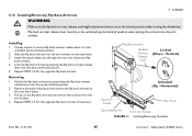
... armrest by pressing the flip back armrest release lever into the arm sockets. Horizontal) Seat Frame Quick-Release Pin Front Arm Socket FIGURE 11 Installing/Removing Footrests Part No 1143192 45 Invacare® Adjustable ASBA Seats Install the quick-release pin through the rear arm socket and flip back armrest. 4. Installing 1. Vertical) Unlocked (Up - Visually...
... armrest by pressing the flip back armrest release lever into the arm sockets. Horizontal) Seat Frame Quick-Release Pin Front Arm Socket FIGURE 11 Installing/Removing Footrests Part No 1143192 45 Invacare® Adjustable ASBA Seats Install the quick-release pin through the rear arm socket and flip back armrest. 4. Installing 1. Vertical) Unlocked (Up - Visually...
Owners Manual 3
Page 46
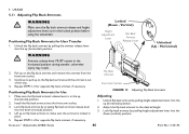
...locked position before using the wheelchair. Adjust the flip back armrest to pull up on the flip back armrest and remove the armrest from the front arm socket. 3. Install the flip back armrest into the up (horizontal) position. Unlock flip back armrest by pulling ...armrest release lever is locked in the horizontal position during transfer, otherwise injury may result. 2. Flip Back Armrest Front Arm Socket FIGURE 12 Adjusting Flip Back Armrests Adjusting 1. Invacare® Adjustable ASBA Seats 46 Part No 1143192 Continue to the desired height. 3. 5 USAGE 5.11 Adjusting Flip...
...locked position before using the wheelchair. Adjust the flip back armrest to pull up on the flip back armrest and remove the armrest from the front arm socket. 3. Install the flip back armrest into the up (horizontal) position. Unlock flip back armrest by pulling ...armrest release lever is locked in the horizontal position during transfer, otherwise injury may result. 2. Flip Back Armrest Front Arm Socket FIGURE 12 Adjusting Flip Back Armrests Adjusting 1. Invacare® Adjustable ASBA Seats 46 Part No 1143192 Continue to the desired height. 3. 5 USAGE 5.11 Adjusting Flip...
Owners Manual 3
Page 59
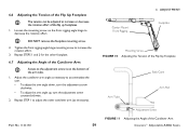
... angle hinge to decrease the rotation effort. DO NOT remove the footplate mounting screw. 2. Repeat STEPS 1 and 2 for the other cantilever arm (as necessary to accommodate the user. • To adjust the arm angle down, turn the adjustment screw counterclockwise. 2. Tighten the front...Tension of the Flip Up Footplate The tension can be adjusted to increase or decrease the rotation effort of the Cantilever Arm 59 Invacare® Adjustable ASBA Seats Center Mount Front Rigging 6 ADJUSTMENT Footplate Mounting Screw FIGURE 10 Adjusting the Tension of the Flip Up ...
... angle hinge to decrease the rotation effort. DO NOT remove the footplate mounting screw. 2. Repeat STEPS 1 and 2 for the other cantilever arm (as necessary to accommodate the user. • To adjust the arm angle down, turn the adjustment screw counterclockwise. 2. Tighten the front...Tension of the Flip Up Footplate The tension can be adjusted to increase or decrease the rotation effort of the Cantilever Arm 59 Invacare® Adjustable ASBA Seats Center Mount Front Rigging 6 ADJUSTMENT Footplate Mounting Screw FIGURE 10 Adjusting the Tension of the Flip Up ...
Owners Manual 3
Page 71
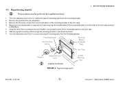
...the inside of the mounting bracket to the desired position. 7. Mounting Bracket Hex Mounting Screws Mounting Bracket (Threaded Plate) Arm Tube Washers Adjustment Lock Lever Joystick not shown. Turn the adjustment lock lever to secure the joystick mounting tube into... the mounting bracket. Remove the joystick from the mounting bracket. 2. FIGURE 6 Repositioning Joystick Joystick Mounting Tube Part No 1143192 71 Invacare® Adjustable ASBA Seats Using the three hex mounting screws and washers, secure...
...the inside of the mounting bracket to the desired position. 7. Mounting Bracket Hex Mounting Screws Mounting Bracket (Threaded Plate) Arm Tube Washers Adjustment Lock Lever Joystick not shown. Turn the adjustment lock lever to secure the joystick mounting tube into... the mounting bracket. Remove the joystick from the mounting bracket. 2. FIGURE 6 Repositioning Joystick Joystick Mounting Tube Part No 1143192 71 Invacare® Adjustable ASBA Seats Using the three hex mounting screws and washers, secure...
Owners Manual 4
Page 35
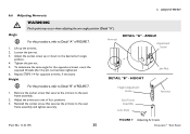
...armrest to Detail "A" of FIGURE 7. 1. HEIGHT Height Adjustment Holes Seat Frame Assembly Lock Knob Jam Nut Armrest Part No 1143195 FIGURE 7 Adjusting Armrests 35 Invacare® Van Seat Adjust the socket screw up the armrest. 2. Armrest DETAIL "A" - Height For this procedure, refer to the seat frame ... seat frame assembly and tighten securely. Angle For this procedure, refer to one of FIGURE 7. 1. Tighten the jam nut. 5. Remove the socket screw that secures the armrest to the desired arm angle position. 4. ANGLE Adjustment Screw DETAIL "B" -
...armrest to Detail "A" of FIGURE 7. 1. HEIGHT Height Adjustment Holes Seat Frame Assembly Lock Knob Jam Nut Armrest Part No 1143195 FIGURE 7 Adjusting Armrests 35 Invacare® Van Seat Adjust the socket screw up the armrest. 2. Armrest DETAIL "A" - Height For this procedure, refer to the seat frame ... seat frame assembly and tighten securely. Angle For this procedure, refer to one of FIGURE 7. 1. Tighten the jam nut. 5. Remove the socket screw that secures the armrest to the desired arm angle position. 4. ANGLE Adjustment Screw DETAIL "B" -
Owners Manual
Page 95
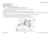
...Seats For this procedure, refer to release the joystick mounting tube from the wheelchair. 3. Remove the three hex screws that secure both halves of the mounting bracket to the arm tube. 6. Turn the adjustment lock lever to 7.10. Turn the adjustment lock lever to the ... bracket on opposite arm tube ensuring the threaded plate of the mounting bracket is on the inside of the arm tube as shown in 7.10. 5. This procedure must be performed by a qualified technician. 1. Remove the joystick from the mounting bracket. 2. Adjustable ASBA Seats 95 Invacare® TDX®...
...Seats For this procedure, refer to release the joystick mounting tube from the wheelchair. 3. Remove the three hex screws that secure both halves of the mounting bracket to the arm tube. 6. Turn the adjustment lock lever to 7.10. Turn the adjustment lock lever to the ... bracket on opposite arm tube ensuring the threaded plate of the mounting bracket is on the inside of the arm tube as shown in 7.10. 5. This procedure must be performed by a qualified technician. 1. Remove the joystick from the mounting bracket. 2. Adjustable ASBA Seats 95 Invacare® TDX®...

