
Owners Manual
Page 3
... - Mechanical ...25 Troubleshooting - Electrical...25 SPJ+, SPJ+ w/PSS or SPJ+ w/ACC Joysticks 25 MPJ+, PSR+, PSF+ Joysticks or Displays 27 Checking Battery Charge Level...29 Part No 1122145 3 Pronto® M94™ TABLE OF CONTENTS TABLE OF CONTENTS REFERENCE DOCUMENTS 2 REGISTER YOUR PRODUCT 6 SPECIAL NOTES 7 LABEL LOCATIONS 9 TYPICAL PRODUCT PARAMETERS 10 SECTION...
... - Mechanical ...25 Troubleshooting - Electrical...25 SPJ+, SPJ+ w/PSS or SPJ+ w/ACC Joysticks 25 MPJ+, PSR+, PSF+ Joysticks or Displays 27 Checking Battery Charge Level...29 Part No 1122145 3 Pronto® M94™ TABLE OF CONTENTS TABLE OF CONTENTS REFERENCE DOCUMENTS 2 REGISTER YOUR PRODUCT 6 SPECIAL NOTES 7 LABEL LOCATIONS 9 TYPICAL PRODUCT PARAMETERS 10 SECTION...
Owners Manual
Page 6
... laws and regulations. Register ONLINE at warranty.invacare.com Please have your model number and purchase date available to Charge Batteries ...75 SPJ+ Joysticks ...75 MPJ+ Joystick...76 Battery Charger Operation...76 On-Board Battery Charger...76 Independent Charger ...78 GLOBAL LIMITED ...WARRANTY (EXCLUDING CANADA 79 CANADA LIMITED WARRANTY 80 REGISTER YOUR PRODUCT The benefits of your product. 3. Pronto® M94™...
... laws and regulations. Register ONLINE at warranty.invacare.com Please have your model number and purchase date available to Charge Batteries ...75 SPJ+ Joysticks ...75 MPJ+ Joystick...76 Battery Charger Operation...76 On-Board Battery Charger...76 Independent Charger ...78 GLOBAL LIMITED ...WARRANTY (EXCLUDING CANADA 79 CANADA LIMITED WARRANTY 80 REGISTER YOUR PRODUCT The benefits of your product. 3. Pronto® M94™...
Owners Manual
Page 10
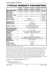
...Refer to how their unique conditions impact their wheelchair. Back height without headrest. 2. Pronto® M94™ 10 Part No 1122145 Variances in battery condition, user weight, usage pattern or overall terrain conditions will result in ANSI/RESNA WC/VOL2...WIDTH (NO JOYSTICK): OVERALL HEIGHT: OVERALL LENGTH: DRIVE WHEELS/TIRES: CASTER W/PRECISION SEALED BEARINGS: FOOTRESTS/ LEGRESTS: WEIGHT2: W/O BATTERIES: W/BATTERIES: SHIPPING: ARMRESTS: BATTERIES: PERFORMANCE: SPEED: TURNING RADIUS: *RANGE (VARIABLE): **WEIGHT LIMITATION: 18-INCH VAN SEAT 18 inches 16 -18 inches 20-...
...Refer to how their unique conditions impact their wheelchair. Back height without headrest. 2. Pronto® M94™ 10 Part No 1122145 Variances in battery condition, user weight, usage pattern or overall terrain conditions will result in ANSI/RESNA WC/VOL2...WIDTH (NO JOYSTICK): OVERALL HEIGHT: OVERALL LENGTH: DRIVE WHEELS/TIRES: CASTER W/PRECISION SEALED BEARINGS: FOOTRESTS/ LEGRESTS: WEIGHT2: W/O BATTERIES: W/BATTERIES: SHIPPING: ARMRESTS: BATTERIES: PERFORMANCE: SPEED: TURNING RADIUS: *RANGE (VARIABLE): **WEIGHT LIMITATION: 18-INCH VAN SEAT 18 inches 16 -18 inches 20-...
Owners Manual
Page 13
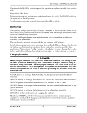
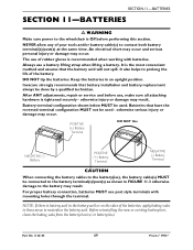
...of improper extension cord could result in the wheelchair while charging the batteries. READ and CAREFULLY follow the manufacturer's instructions for a positive lock. Part No 1122145 13 Pronto® M94™ SECTION 1-GENERAL GUIDELINES The detent balls MUST be protruding past... consult a qualified technician for these applications. Carefully read battery/battery charger information prior to the battery terminals. Avoid storage or use only a three wire extension cord having at the same time. Invacare strongly recommends their use of moisture. DO NOT operate ...
...of improper extension cord could result in the wheelchair while charging the batteries. READ and CAREFULLY follow the manufacturer's instructions for a positive lock. Part No 1122145 13 Pronto® M94™ SECTION 1-GENERAL GUIDELINES The detent balls MUST be protruding past... consult a qualified technician for these applications. Carefully read battery/battery charger information prior to the battery terminals. Avoid storage or use only a three wire extension cord having at the same time. Invacare strongly recommends their use of moisture. DO NOT operate ...

Owners Manual
Page 14
...two‐ prong wall receptacle is encountered, it is not torn or cracked where water can enter and that the RED and BLACK battery terminal caps are secured in accordance with ISO 7176 "Rain Test." This provides the end user or his/her assistant sufficient time to...hazards and fire. Some devices are equipped with SureStep has a weight limitation of 500 lbs. Weight Limitation The M94 with three‐prong (grounding) plugs for Invacare products. In addition, Invacare has placed RED/ORANGE warning tags on the charger. If occupant uses said wheelchair as a weight training apparatus...
...two‐ prong wall receptacle is encountered, it is not torn or cracked where water can enter and that the RED and BLACK battery terminal caps are secured in accordance with ISO 7176 "Rain Test." This provides the end user or his/her assistant sufficient time to...hazards and fire. Some devices are equipped with SureStep has a weight limitation of 500 lbs. Weight Limitation The M94 with three‐prong (grounding) plugs for Invacare products. In addition, Invacare has placed RED/ORANGE warning tags on the charger. If occupant uses said wheelchair as a weight training apparatus...

Owners Manual
Page 19
...MUST be inadvertently released, resulting in injury to the user or damage to avoid injury. Use proper lifting techniques (lift with batteries and without the user is strongly recommended to lift the wheelchair only by means of user and wheelchair (for hand-hold supports... seat. It is 290 lbs. Part No 1122145 19 Pronto® M94™ When learning a new assistance technique, have an experienced assistant help you before attempting it is advised when it alone. Invacare recommends using two assistants and making thorough preparations. Ensure that driving surfaces,...
...MUST be inadvertently released, resulting in injury to the user or damage to avoid injury. Use proper lifting techniques (lift with batteries and without the user is strongly recommended to lift the wheelchair only by means of user and wheelchair (for hand-hold supports... seat. It is 290 lbs. Part No 1122145 19 Pronto® M94™ When learning a new assistance technique, have an experienced assistant help you before attempting it is advised when it alone. Invacare recommends using two assistants and making thorough preparations. Ensure that driving surfaces,...

Owners Manual
Page 26
... of-Neutral-at-Power-Up to Connecting/Disconnecting the Battery Wiring Harness on . Check that battery cables are on implies reduced battery charge. Contact Invacare/Dealer for service. Power is flashing. Left RED LED is off . Contact Invacare/Dealer for service. Contact Invacare/Dealer for service. Pronto® M94™ 26 Part No 1122145 Fewer than three...
... of-Neutral-at-Power-Up to Connecting/Disconnecting the Battery Wiring Harness on . Check that battery cables are on implies reduced battery charge. Contact Invacare/Dealer for service. Power is flashing. Left RED LED is off . Contact Invacare/Dealer for service. Contact Invacare/Dealer for service. Pronto® M94™ 26 Part No 1122145 Fewer than three...

Owners Manual
Page 27
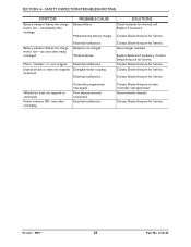
... the reverse, forward, left or right limits (Error codes E01, E02, E03 or E04). Battery failure. Contact Dealer/Invacare for shorted cell. Part No 1122145 27 Pronto® M94™ CHARGER PLUGGED IN displays. Refer to Installing/ Removing the Batteries on page 66. disconnected (Error code 32). SECTION 4-SAFETY INSPECTION/TROUBLESHOOTING MPJ+, PSR+, PSF...
... the reverse, forward, left or right limits (Error codes E01, E02, E03 or E04). Battery failure. Contact Dealer/Invacare for shorted cell. Part No 1122145 27 Pronto® M94™ CHARGER PLUGGED IN displays. Refer to Installing/ Removing the Batteries on page 66. disconnected (Error code 32). SECTION 4-SAFETY INSPECTION/TROUBLESHOOTING MPJ+, PSR+, PSF...
Owners Manual
Page 28
... reprogrammed. Electrical malfunction. Contact Dealer/Invacare to commands. Pronto® M94™ 28 Part No 1122145 immediately after being recharged. Batteries not charged. Contact Dealer/Invacare for shorted cell. Power indicator Off - Contact Dealer/Invacare for Service. Contact Dealer/Invacare for Service. even after recharging. Have terminals cleaned. Weak batteries. PROBABLE CAUSE Battery failure. Damaged motor coupling. Malfunctioning...
... reprogrammed. Electrical malfunction. Contact Dealer/Invacare to commands. Pronto® M94™ 28 Part No 1122145 immediately after being recharged. Batteries not charged. Contact Dealer/Invacare for shorted cell. Power indicator Off - Contact Dealer/Invacare for Service. Contact Dealer/Invacare for Service. even after recharging. Have terminals cleaned. Weak batteries. PROBABLE CAUSE Battery failure. Damaged motor coupling. Malfunctioning...

Owners Manual
Page 29
... in this manual. Don't tip or tilt batteries. Part No 1122145 29 Pronto® M94™ Fully charge a new battery before charging. Use a carrying strap to maintain a high charge level and extend battery life. Use only a GEL charger for your battery and chargers. SECTION 4-SAFETY INSPECTION/TROUBLESHOOTING Checking Battery Charge Level The following "Do's" and "Don...
... in this manual. Don't tip or tilt batteries. Part No 1122145 29 Pronto® M94™ Fully charge a new battery before charging. Use a carrying strap to maintain a high charge level and extend battery life. Use only a GEL charger for your battery and chargers. SECTION 4-SAFETY INSPECTION/TROUBLESHOOTING Checking Battery Charge Level The following "Do's" and "Don...
Owners Manual
Page 33
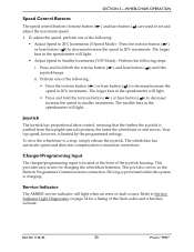
...AMBER service indicator will light. • Press and hold both the tortoise button ( joystick beeps. Part No 1122145 33 Pronto® M94™ To slow the wheelchair to set and adjust the maximum speed. 1. The wheelchair has automatic speed and direction compensation to Service ...Indicator Light Diagnostics on page 34 for charging the wheelchair batteries. The larger bars in the speedometer will light when an error or fault occurs. Charger/Programming Input The charger/programming input is...
...AMBER service indicator will light. • Press and hold both the tortoise button ( joystick beeps. Part No 1122145 33 Pronto® M94™ To slow the wheelchair to set and adjust the maximum speed. 1. The wheelchair has automatic speed and direction compensation to Service ...Indicator Light Diagnostics on page 34 for charging the wheelchair batteries. The larger bars in the speedometer will light when an error or fault occurs. Charger/Programming Input The charger/programming input is...
Owners Manual
Page 34
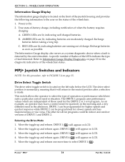
...Mode 1. Move the toggle up and release again. DRIVE 4 ( ) will appear on LCD. 5. RED LEDs are lit, indicating batteries are lit, indicating well charged batteries. The DRIVE 1 program uses performance values which best suits a particular control need or situation. Move the toggle up and release. Move... display also serves as possible. DRIVE 2 ( ) will appear on LCD. 3. Move the toggle up and release again. Pronto® M94™ 34 Part No 1122145 Drive Select Toggle Switch The drive select toggle switch is detected by the control module. DRIVE 1 can be ...
...Mode 1. Move the toggle up and release again. DRIVE 4 ( ) will appear on LCD. 5. RED LEDs are lit, indicating batteries are lit, indicating well charged batteries. The DRIVE 1 program uses performance values which best suits a particular control need or situation. Move the toggle up and release. Move... display also serves as possible. DRIVE 2 ( ) will appear on LCD. 3. Move the toggle up and release again. Pronto® M94™ 34 Part No 1122145 Drive Select Toggle Switch The drive select toggle switch is detected by the control module. DRIVE 1 can be ...

Owners Manual
Page 35
... To slow the wheelchair to minimize corrections. This port also serves as the Remote Programmer Communication connection. Part No 1122145 35 Pronto® M94™ Charger/Programming Input The charger/programming input is readable in front of the joystick and provides information on the side of the joystick ...knob counterclockwise (backward) to decrease the speed of the wheelchair to the programmed max speed. This provides easy access for charging the wheelchair batteries. Rotate the knob clockwise (forward) to increase the speed of the wheelchair to the programmed max speed. 2.
... To slow the wheelchair to minimize corrections. This port also serves as the Remote Programmer Communication connection. Part No 1122145 35 Pronto® M94™ Charger/Programming Input The charger/programming input is readable in front of the joystick and provides information on the side of the joystick ...knob counterclockwise (backward) to decrease the speed of the wheelchair to the programmed max speed. This provides easy access for charging the wheelchair batteries. Rotate the knob clockwise (forward) to increase the speed of the wheelchair to the programmed max speed. 2.

Owners Manual
Page 36
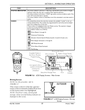
... instructions. The lower half of the LCD display is displayed in the upper half of information shown. Pronto® M94™ 36 Part No 1122145 Available choices are as possible. This screen displays the software version and date information. This symbol shows... the Battery Level and will progressively disappear until no segments appear between E (Empty) and F (Full). FIGURE 5.5 LCD Display Screens - Battery charge level is displayed at startup of the joystick for descriptions of the LCD...
... instructions. The lower half of the LCD display is displayed in the upper half of information shown. Pronto® M94™ 36 Part No 1122145 Available choices are as possible. This screen displays the software version and date information. This symbol shows... the Battery Level and will progressively disappear until no segments appear between E (Empty) and F (Full). FIGURE 5.5 LCD Display Screens - Battery charge level is displayed at startup of the joystick for descriptions of the LCD...
Owners Manual
Page 37
... an Attendant Icon if the attendant's override switch is active. NOTE: The Drive's name, warning/info message, status icon and battery indicator are based upon the configuration of the chair. SECTION 5-WHEELCHAIR OPERATION ITEM STATUS INDICATOR MODES DESCRIPTION The status indicator will show... highlighted. FIGURE 5.7 LCD Display Screens - Driving Screen Part No 1122145 37 Pronto® M94™ The chair will not be Programmed) Drive Profile Name Drive Indicator Battery Gauge Display Icon appears when a joystick command will drive the wheelchair Status/Info Message Area...
... an Attendant Icon if the attendant's override switch is active. NOTE: The Drive's name, warning/info message, status icon and battery indicator are based upon the configuration of the chair. SECTION 5-WHEELCHAIR OPERATION ITEM STATUS INDICATOR MODES DESCRIPTION The status indicator will show... highlighted. FIGURE 5.7 LCD Display Screens - Driving Screen Part No 1122145 37 Pronto® M94™ The chair will not be Programmed) Drive Profile Name Drive Indicator Battery Gauge Display Icon appears when a joystick command will drive the wheelchair Status/Info Message Area...
Owners Manual
Page 69
... injury or damage may occur. NOTE: If there is the most convenient method and assures that the battery acid will not spill. Part No 1122145 69 Pronto® M94™ Always use post style terminals with batteries. Invacare strongly recommends that have the reversed terminal configuration MUST not be done by a qualified technician. An...
... injury or damage may occur. NOTE: If there is the most convenient method and assures that the battery acid will not spill. Part No 1122145 69 Pronto® M94™ Always use post style terminals with batteries. Invacare strongly recommends that have the reversed terminal configuration MUST not be done by a qualified technician. An...
Owners Manual
Page 70
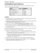
... Assembly on one of FIGURE 11.1). 7. Place the wheelchair in the Off position and disconnect joystick. Refer to position the battery into the battery tray. Move aside the motor leads and controller cable to allow unobstructed access to FIGURE 11.1 on page 71 and FIGURE ...inch (6pt) Box Wrench Diagonal Cutters QTY 1 1 1 1 1 COMMENTS Supplied Not Supplied Not Supplied Not Supplied Not Supplied Installing 1. Pronto® M94™ 70 Part No 1122145 Remove the seat. NOTE: Perform this procedure, refer to the front of FIGURE 11.1). If necessary, connect the wiring harness...
... Assembly on one of FIGURE 11.1). 7. Place the wheelchair in the Off position and disconnect joystick. Refer to position the battery into the battery tray. Move aside the motor leads and controller cable to allow unobstructed access to FIGURE 11.1 on page 71 and FIGURE ...inch (6pt) Box Wrench Diagonal Cutters QTY 1 1 1 1 1 COMMENTS Supplied Not Supplied Not Supplied Not Supplied Not Supplied Installing 1. Pronto® M94™ 70 Part No 1122145 Remove the seat. NOTE: Perform this procedure, refer to the front of FIGURE 11.1). If necessary, connect the wiring harness...
Owners Manual
Page 71
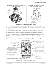
...) MUST be reduced. 14. Retaining Strap FIGURE 11.2 Installing/Removing the Batteries Part No 1122145 71 Pronto® M94™ Refer to Removing/Installing the Shrouds on page 50. 13. Refer to Disconnecting/Connecting the Joysticks on page 74. Refer to Removing/...Installing the Seat Assembly on page 65. 12. If necessary, charge the battery(ies). Connect the front battery to FIGURE 11.2. 11. ...
...) MUST be reduced. 14. Retaining Strap FIGURE 11.2 Installing/Removing the Batteries Part No 1122145 71 Pronto® M94™ Refer to Removing/Installing the Shrouds on page 50. 13. Refer to Disconnecting/Connecting the Joysticks on page 74. Refer to Removing/...Installing the Seat Assembly on page 65. 12. If necessary, charge the battery(ies). Connect the front battery to FIGURE 11.2. 11. ...

Owners Manual
Page 72
... (+) RED cable to remove remaining battery from batteries. If necessary, disconnect the wiring harness from battery tray. 10. Use the exposed, threaded portion of FIGURE 11.1). • Batteries without risking damage to the front battery wiring harness. Pronto® M94™ 72 Part No 1122145 Disconnect the front battery from POSITIVE (+) RED battery cable/mounting screw. NOTE: Both...
... (+) RED cable to remove remaining battery from batteries. If necessary, disconnect the wiring harness from battery tray. 10. Use the exposed, threaded portion of FIGURE 11.1). • Batteries without risking damage to the front battery wiring harness. Pronto® M94™ 72 Part No 1122145 Disconnect the front battery from POSITIVE (+) RED battery cable/mounting screw. NOTE: Both...
Owners Manual
Page 73
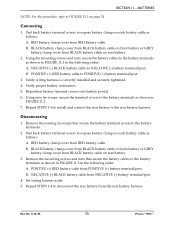
... 11.3 in the following order: A. NEGATIVE (‐) BLACK battery cable from RED battery cable. Connecting 1. Peel back battery terminal covers to disconnect the rear battery from BLACK battery cable on rear battery. 2. B. Verify proper battery orientation. 5. RED battery clamp cover from NEGATIVE (‐) battery terminal/post. 4. POSITIVE (+) RED battery cable from RED battery cable. Set wiring harness aside. 5. B. B. Repeat STEPS 1‐...
... 11.3 in the following order: A. NEGATIVE (‐) BLACK battery cable from RED battery cable. Connecting 1. Peel back battery terminal covers to disconnect the rear battery from BLACK battery cable on rear battery. 2. B. Verify proper battery orientation. 5. RED battery clamp cover from NEGATIVE (‐) battery terminal/post. 4. POSITIVE (+) RED battery cable from RED battery cable. Set wiring harness aside. 5. B. B. Repeat STEPS 1‐...


