SR1500 Chassis TPS
Page 5
... Boards 53 9.1 Intel® Server Board S5000PAL 53 9.1.1 Processor Support 56 10. PCI Riser Cards and Assembly 48 8.1 Riser Card Options 49 9. Standard Control Panel ...38 6.1 Control Panel Buttons 39 6.2 Control Panel LED Indicators 39 6.2.1 Power / Sleep LED 40 6.2.2 System Status LED 41 6.2.3 Drive Activity LED 42 6.2.4 System Identification LED 42 6.3 Control Panel Connectors 42 7. Environmental and Regulatory Specifications 57 10.1 System Level Environmental Limits 57 10.2 Serviceability and Availability 57 10.3 Replacing the Back up Battery...
... Boards 53 9.1 Intel® Server Board S5000PAL 53 9.1.1 Processor Support 56 10. PCI Riser Cards and Assembly 48 8.1 Riser Card Options 49 9. Standard Control Panel ...38 6.1 Control Panel Buttons 39 6.2 Control Panel LED Indicators 39 6.2.1 Power / Sleep LED 40 6.2.2 System Status LED 41 6.2.3 Drive Activity LED 42 6.2.4 System Identification LED 42 6.3 Control Panel Connectors 42 7. Environmental and Regulatory Specifications 57 10.1 System Level Environmental Limits 57 10.2 Serviceability and Availability 57 10.3 Replacing the Back up Battery...
SR1500 Chassis TPS
Page 7
... 6. Hard Drive Carrier...18 Figure 17. Standard Control Panel Assembly Module 38 Figure 27. Control Panel LED Indicators 39 Figure 29. LCD Control Panel Overview 5 Figure 9. Control Panel Buttons 39 Figure 28. Front View without Bezel - Showing the Standard Control Panel Option 1 Figure 3. Rear Chassis View ...1 Figure 4. Control Panel Modules 4 Figure 7. Drive Bay Overview ...6 Figure 10. Fan Module Assembly 15 Figure 14. Hot-swap Active SAS Backplane Functional Diagram 27 Figure 25. PCI Riser Card Assembly - Air Baffle ...17 Figure 15. Intel...
... 6. Hard Drive Carrier...18 Figure 17. Standard Control Panel Assembly Module 38 Figure 27. Control Panel LED Indicators 39 Figure 29. LCD Control Panel Overview 5 Figure 9. Control Panel Buttons 39 Figure 28. Front View without Bezel - Showing the Standard Control Panel Option 1 Figure 3. Rear Chassis View ...1 Figure 4. Control Panel Modules 4 Figure 7. Drive Bay Overview ...6 Figure 10. Fan Module Assembly 15 Figure 14. Hot-swap Active SAS Backplane Functional Diagram 27 Figure 25. PCI Riser Card Assembly - Air Baffle ...17 Figure 15. Intel...

SR1500 Chassis TPS
Page 15
...) C PCI card bracket (full height) D AC Power Receptacle E Management Network Interface (optional) F IO module external connector (optional) G USB 1 connector H USB 2 connector I Video connector J NIC 1 connector K NIC 2 connector L RJ45 serial B port M PS2 keyboard connector TP02155 1.4 System Boards The complete system includes the use of several system boards which are pre-cut, so the use of an I/O shield is not required. Available riser card options for each. • Bridge Board - PCB used to provide up to two add-in adapter. • Riser Cards - cable less...
...) C PCI card bracket (full height) D AC Power Receptacle E Management Network Interface (optional) F IO module external connector (optional) G USB 1 connector H USB 2 connector I Video connector J NIC 1 connector K NIC 2 connector L RJ45 serial B port M PS2 keyboard connector TP02155 1.4 System Boards The complete system includes the use of several system boards which are pre-cut, so the use of an I/O shield is not required. Available riser card options for each. • Bridge Board - PCB used to provide up to two add-in adapter. • Riser Cards - cable less...

SR1500 Chassis TPS
Page 16
... is used to enable the software SATA RAID 5 functionality of the ESB2 SATA ports of the server board when cabled to the passive backplane or the SAS RAID 5 functionality of the active backplane. 1.5 Control Panel Options The server chassis can support either of the chassis. The control panel assemblies are available for this system o Standard Control Panel (Product Code - The entire module assembly slides into a connector on the server board or the Active back-plane. This RAID key plugs into a predefined slot...
... is used to enable the software SATA RAID 5 functionality of the ESB2 SATA ports of the server board when cabled to the passive backplane or the SAS RAID 5 functionality of the active backplane. 1.5 Control Panel Options The server chassis can support either of the chassis. The control panel assemblies are available for this system o Standard Control Panel (Product Code - The entire module assembly slides into a connector on the server board or the Active back-plane. This RAID key plugs into a predefined slot...

SR1500 Chassis TPS
Page 18
... be used to three hot-swappable SAS (Serial Attach-SCSI) or SATA (Serial ATA) hard drives and one slimline optical device. Drive Bay Overview A Slimline drive bay (drive not included) B Control panel (standard control panel shown) C Hard Drive Status LEDs D Hard drive bays (drives not included) TP02156 1.7 Power Sub-system The power sub-system of the chassis consists of an Intel® Remote Management Module and Intel® System Management Software, the power subsystem is designed to support a single slimline IDE optical drive or a slimline USB floppy drive. Product...
... be used to three hot-swappable SAS (Serial Attach-SCSI) or SATA (Serial ATA) hard drives and one slimline optical device. Drive Bay Overview A Slimline drive bay (drive not included) B Control panel (standard control panel shown) C Hard Drive Status LEDs D Hard drive bays (drives not included) TP02156 1.7 Power Sub-system The power sub-system of the chassis consists of an Intel® Remote Management Module and Intel® System Management Software, the power subsystem is designed to support a single slimline IDE optical drive or a slimline USB floppy drive. Product...

SR1500 Chassis TPS
Page 19
... 1.4 7 Intel order number D31981-008 In addition, a chassis intrusion switch is integrated into either a 2-post rack or 4-post cabinet • A tool-less full extracting slide rail kit (Product order code - AXXBRACKETS ) which prevents unauthorized access to 30" deep server cabinets. Maximum input current at low input voltage range shall be configured to mount the system into the low profile riser allowing server management software to monitor removal of the top cover...
... 1.4 7 Intel order number D31981-008 In addition, a chassis intrusion switch is integrated into either a 2-post rack or 4-post cabinet • A tool-less full extracting slide rail kit (Product order code - AXXBRACKETS ) which prevents unauthorized access to 30" deep server cabinets. Maximum input current at low input voltage range shall be configured to mount the system into the low profile riser allowing server management software to monitor removal of the top cover...
SR1500 Chassis TPS
Page 27
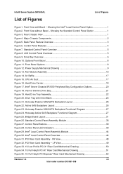
... which connects to the hotswap backplane. Should a fan fail, the system should be monitored independently by Intel® System Management Software. Fans are individually replaceable through a connection to the hot-swap backplane. The fifth dual rotor fan provides the primary cooling for the processors, memory, second and third hard drive bays, and components in the low profile PCI zone. The server must be replaced. Note: The Intel® Server Chassis SR1500 does not support redundant...
... which connects to the hotswap backplane. Should a fan fail, the system should be monitored independently by Intel® System Management Software. Fans are individually replaceable through a connection to the hot-swap backplane. The fifth dual rotor fan provides the primary cooling for the processors, memory, second and third hard drive bays, and components in the low profile PCI zone. The server must be replaced. Note: The Intel® Server Chassis SR1500 does not support redundant...

SR1500 Chassis TPS
Page 32
... bay. The hard drive bays are not hot-swappable. 5.1.1 USB Floppy Drive Support With an optional floppy drive installation kit, the chassis can be configured for an IDE optical CD-ROM, DVD/CDR, or USB floppy drive. Table 14. 4-pin USB Floppy Connector Pin-out Pin Name 1 Power 2 USB_P3n 3 USB P3p 4 Ground 20 Revision 1.4 Intel order number D31981-008 The floppy drive can support a slimline USB floppy drive. The option kit includes the necessary cables and trays...
... bay. The hard drive bays are not hot-swappable. 5.1.1 USB Floppy Drive Support With an optional floppy drive installation kit, the chassis can be configured for an IDE optical CD-ROM, DVD/CDR, or USB floppy drive. Table 14. 4-pin USB Floppy Connector Pin-out Pin Name 1 Power 2 USB_P3n 3 USB P3p 4 Ground 20 Revision 1.4 Intel order number D31981-008 The floppy drive can support a slimline USB floppy drive. The option kit includes the necessary cables and trays...

SR1500 Chassis TPS
Page 40
... specification by providing management data to ensure reliable data transfers, while providing the connectivity and flexibility of the PCI Express bus limits the electrical load on " systems. Enhanced error handling features, such as wide or narrow. Hot-Plug/Hot-Swap support enables "always-on links, allowing increased transmission and reception frequencies. The SAS interface uses the proven SCSI command set to the baseboard management controller on the server board. 5.3.3 LSI* SAS1064E 3.0 Gbit/s Serial Attached SCSI Controller...
... specification by providing management data to ensure reliable data transfers, while providing the connectivity and flexibility of the PCI Express bus limits the electrical load on " systems. Enhanced error handling features, such as wide or narrow. Hot-Plug/Hot-Swap support enables "always-on links, allowing increased transmission and reception frequencies. The SAS interface uses the proven SCSI command set to the baseboard management controller on the server board. 5.3.3 LSI* SAS1064E 3.0 Gbit/s Serial Attached SCSI Controller...

SR1500 Chassis TPS
Page 41
...; Provides drive spin-up sequencing control • Provides up to two LED signals for each SAS/SATA phy to -point, enterprise-level storage interface • Supports wide transfers consisting of 2, 3, or 4 phys • Supports narrow ports consisting of the I /Os and minimizes system bus overhead by completely managing all integrated RAID capabilities. A single firmware build supports all I /O bus. For non-RAID SAS configurations, the LSISAS1064E uses the Fusion-MPT* (Message Passing...
...; Provides drive spin-up sequencing control • Provides up to two LED signals for each SAS/SATA phy to -point, enterprise-level storage interface • Supports wide transfers consisting of 2, 3, or 4 phys • Supports narrow ports consisting of the I /Os and minimizes system bus overhead by completely managing all integrated RAID capabilities. A single firmware build supports all I /O bus. For non-RAID SAS configurations, the LSISAS1064E uses the Fusion-MPT* (Message Passing...

SR1500 Chassis TPS
Page 42
... Revision 1.4 Intel order number D31981-008 LED Function Status LED GREEN AMBER Definition HDD Activity HDD Fail The activity LED functionality is used in a RAID configuration, the RAID controller will illuminate green for activity or amber for each of the hard drive connectors. The expected operation is detected. The LED will have control over the fault LED and it may exhibit different behavior. Peripheral and Hard Drive Support Intel® Server System SR1500AL TPS 5.3.4 LED Support The backplanes support an activity/fault LED for a drive fault.
... Revision 1.4 Intel order number D31981-008 LED Function Status LED GREEN AMBER Definition HDD Activity HDD Fail The activity LED functionality is used in a RAID configuration, the RAID controller will illuminate green for activity or amber for each of the hard drive connectors. The expected operation is detected. The LED will have control over the fault LED and it may exhibit different behavior. Peripheral and Hard Drive Support Intel® Server System SR1500AL TPS 5.3.4 LED Support The backplanes support an activity/fault LED for a drive fault.

SR1500 Chassis TPS
Page 47
... 4 GROUND Revision 1.4 35 Intel order number D31981-008 These are used to attach SATA/SAS cables from the backplane to either the slimline drive bay or in one of the hard drive bays, the USB floppy cable is routed from the drive to SAS/SATA ports from an add-in card. Each drive control connector has the following table provides the pin-out for the floppy drive connector. Table 23. SATA/SAS Drive Control Connector Pin-out (J3C1...
... 4 GROUND Revision 1.4 35 Intel order number D31981-008 These are used to attach SATA/SAS cables from the backplane to either the slimline drive bay or in one of the hard drive bays, the USB floppy cable is routed from the drive to SAS/SATA ports from an add-in card. Each drive control connector has the following table provides the pin-out for the floppy drive connector. Table 23. SATA/SAS Drive Control Connector Pin-out (J3C1...

SR1500 Chassis TPS
Page 52
... hard disk activity Blue On System Identification Off Off Identify active via command or button. Blink rate is ~1 Hz with at 50% duty cycle. 2. The power LED sleep indication is off due to a failure or configuration change that prevents the BIOS from running . S0 ACPI Steady on until the BIOS clears it is possible that the system status LED is maintained on standby power) Green/Amber Green Amber Alternating Blink...
... hard disk activity Blue On System Identification Off Off Identify active via command or button. Blink rate is ~1 Hz with at 50% duty cycle. 2. The power LED sleep indication is off due to a failure or configuration change that prevents the BIOS from running . S0 ACPI Steady on until the BIOS clears it is possible that the system status LED is maintained on standby power) Green/Amber Green Amber Alternating Blink...

SR1500 Chassis TPS
Page 53
...; Unable to use all of operational fans should light up . This does not apply to a spare DIMM (memory sparing). BMC Initialization When AC power is first applied to initialize. Control Panel buttons are two processors and one DIMM installed). • Correctable errors over a threshold of them fails • Fan alarm - This is applied to cool the system • Non-critical threshold crossed - power fault • Processor configuration error (for instance, processor stepping mismatch) 6.2.2.1 System Status LED - Control Panel LED Operation...
...; Unable to use all of operational fans should light up . This does not apply to a spare DIMM (memory sparing). BMC Initialization When AC power is first applied to initialize. Control Panel buttons are two processors and one DIMM installed). • Correctable errors over a threshold of them fails • Fan alarm - This is applied to cool the system • Non-critical threshold crossed - power fault • Processor configuration error (for instance, processor stepping mismatch) 6.2.2.1 System Status LED - Control Panel LED Operation...

SR1500 Chassis TPS
Page 57
... status LED is powered off . 3. The operating system has saved context to the hard disk. System and the operating system are located on until the BIOS clears it is possible that the Power LED will be blinking at the time of low-power state. When the amber LED is powered on the Intel® Server Board S5000PAL. 7.1.1 Power / Sleep LED Table 35. Also off when the system is off due to a failure or configuration change...
... status LED is powered off . 3. The operating system has saved context to the hard disk. System and the operating system are located on until the BIOS clears it is possible that the Power LED will be blinking at the time of low-power state. When the amber LED is powered on the Intel® Server Board S5000PAL. 7.1.1 Power / Sleep LED Table 35. Also off when the system is off due to a failure or configuration change...

SR1500 Chassis TPS
Page 65
... Connectors/Headers Add-in PCI, PCI-X*, PCI Express* Cards On-board Video On-board Hard Drive Controller LAN System Fans Note: Intel will make available an OEM SKU of this server board using the Intel® 5000X Memory Controller Hub External connections: • Stacked PS/2* ports for keyboard and mouse • RJ45 Serial B port • Two RJ45 NIC connectors for 10/100/1000 Mb connections • Two USB 2.0 ports • Video Connector Internal connectors/headers: • One USB port header, capable of the server board feature sets. Supported Intel® Server Boards The chassis...
... Connectors/Headers Add-in PCI, PCI-X*, PCI Express* Cards On-board Video On-board Hard Drive Controller LAN System Fans Note: Intel will make available an OEM SKU of this server board using the Intel® 5000X Memory Controller Hub External connections: • Stacked PS/2* ports for keyboard and mouse • RJ45 Serial B port • Two RJ45 NIC connectors for 10/100/1000 Mb connections • Two USB 2.0 ports • Video Connector Internal connectors/headers: • One USB port header, capable of the server board feature sets. Supported Intel® Server Boards The chassis...

SR1500 Chassis TPS
Page 68
... P CPU #2 Connector Q CPU #1 Fan Header R Voltage Regulator Heat Sink S CPU #2 Fan Header T Bridge Board Connector U ATA-100 Optical Drive Connector (Power+IO) Description V System Fan #2 Header W CPU Power Connector X Main Power Connector Y Battery Z Power Supply Management Connector AA Dual Port USB 2.0 Header BB System Fan #1 Header CC SSI 24-pin Control Panel Header DD SATA 0 EE SATA 1 FF SATA 2 GG SATA 3 HH SATA 4 II SATA 5 JJ SATA SW RAID 5 Activation Key Connector KK Intel® Remote Management Module (RMM) Connector LL System Recovery Jumper Block MM Chassis Intrusion Switch Header...
... P CPU #2 Connector Q CPU #1 Fan Header R Voltage Regulator Heat Sink S CPU #2 Fan Header T Bridge Board Connector U ATA-100 Optical Drive Connector (Power+IO) Description V System Fan #2 Header W CPU Power Connector X Main Power Connector Y Battery Z Power Supply Management Connector AA Dual Port USB 2.0 Header BB System Fan #1 Header CC SSI 24-pin Control Panel Header DD SATA 0 EE SATA 1 FF SATA 2 GG SATA 3 HH SATA 4 II SATA 5 JJ SATA SW RAID 5 Activation Key Connector KK Intel® Remote Management Module (RMM) Connector LL System Recovery Jumper Block MM Chassis Intrusion Switch Header...

SR1500 Chassis TPS
Page 70
.... 58 Revision 1.4 Intel order number D31981-008 Environmental and Regulatory Specifications Intel® Server System SR1500AL TPS 10.3 Replacing the Back up Battery The lithium battery on virheellisesti asennettu. Eksplosjonsfare. Contact your customer service representative or dealer for up to weaken, it loses voltage, and the server settings stored in CMOS RAM in the absence of power. Discard used batteries according to manufacturer's instructions. Brukt batteri returneres apparatleverand...
.... 58 Revision 1.4 Intel order number D31981-008 Environmental and Regulatory Specifications Intel® Server System SR1500AL TPS 10.3 Replacing the Back up Battery The lithium battery on virheellisesti asennettu. Eksplosjonsfare. Contact your customer service representative or dealer for up to weaken, it loses voltage, and the server settings stored in CMOS RAM in the absence of power. Discard used batteries according to manufacturer's instructions. Brukt batteri returneres apparatleverand...
SR1500 Chassis TPS
Page 80
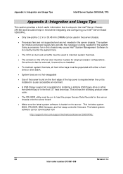
... is removed, it cannot be re-installed. • To maintain system thermals, all hard drive bays must be run to load the proper Sensor Data Records for the server chassis onto the server board. • Make sure the latest system software is loaded on the CPU air duct must be downloaded from http://support.intel.com/support/motherboards/server/S5000PAL/ 68 Revision 1.4 Intel order number D31981-008 The system fan module and power supply fans...
... is removed, it cannot be re-installed. • To maintain system thermals, all hard drive bays must be run to load the proper Sensor Data Records for the server chassis onto the server board. • Make sure the latest system software is loaded on the CPU air duct must be downloaded from http://support.intel.com/support/motherboards/server/S5000PAL/ 68 Revision 1.4 Intel order number D31981-008 The system fan module and power supply fans...
SR1500 Chassis TPS
Page 87
Reference Documents Intel® Server System SR1500AL TPS Reference Documents See the following documents for additional information: o Intel® Server Board S5000PAL Technical Product Specification o Intel® 5000 Series Chipsets Server Board Family Datasheet o Intel® Server Chassis SR1500 AC Power Supply Module Specification o Intel® Server Board S5000PAL/S5000XAL Tested Hardware and OS List o Intel® Server Board S5000PAL/Intel® Server Chassis SR1500 Spares/Parts List and Configuration Guide Intel order number D31981-008 Revision V1.I4II
Reference Documents Intel® Server System SR1500AL TPS Reference Documents See the following documents for additional information: o Intel® Server Board S5000PAL Technical Product Specification o Intel® 5000 Series Chipsets Server Board Family Datasheet o Intel® Server Chassis SR1500 AC Power Supply Module Specification o Intel® Server Board S5000PAL/S5000XAL Tested Hardware and OS List o Intel® Server Board S5000PAL/Intel® Server Chassis SR1500 Spares/Parts List and Configuration Guide Intel order number D31981-008 Revision V1.I4II


