
Service Guide
Page 2
... responsible if components fail or the workstation board does not operate correctly when used together. Intel workstation boards contain a number of high-density VLSI and power delivery components that chooses not to use of Intel products including liability or warranties relating ... merchantability, or infringement of any time, without notice. All Rights Reserved ii Intel® Workstation Board S5520SC Service Guide Disclaimer Disclaimer ® Information in this document. Intel products are designed and tested to specifications and product descriptions at any patent, ...
... responsible if components fail or the workstation board does not operate correctly when used together. Intel workstation boards contain a number of high-density VLSI and power delivery components that chooses not to use of Intel products including liability or warranties relating ... merchantability, or infringement of any time, without notice. All Rights Reserved ii Intel® Workstation Board S5520SC Service Guide Disclaimer Disclaimer ® Information in this document. Intel products are designed and tested to specifications and product descriptions at any patent, ...

Service Guide
Page 4
...devices, and cables: Hazardous electrical conditions may bend or break the pins on /off: The power button DOES NOT turn off the server and disconnect the power cord, telecommunications systems, networks, and modems attached to the server before you perform all procedures .... They can damage disk drives, boards, and other resource as a reference, pay close attention to the safety instructions. Installing or removing jumpers: A jumper is unplugged before opening it. grip the narrow sides of fine needle nosed pliers. iv Intel® Workstation Board S5520SC Service Guide
...devices, and cables: Hazardous electrical conditions may bend or break the pins on /off: The power button DOES NOT turn off the server and disconnect the power cord, telecommunications systems, networks, and modems attached to the server before you perform all procedures .... They can damage disk drives, boards, and other resource as a reference, pay close attention to the safety instructions. Installing or removing jumpers: A jumper is unplugged before opening it. grip the narrow sides of fine needle nosed pliers. iv Intel® Workstation Board S5520SC Service Guide

Service Guide
Page 7
..., and ME), and utilities For software to manage your Intel® server See the section on the web page titled, "Compatibility". Power Budget Analysis Tool. Available at : http://support.intel.com/support/motherboards/server/S5520SC/. Available for download at : http://support.intel.com/support/motherboards/server/S5520SC/. Available at: http://www.intel.com/go/servermanagement Intel® Workstation Board S5520SC Service Guide vii
..., and ME), and utilities For software to manage your Intel® server See the section on the web page titled, "Compatibility". Power Budget Analysis Tool. Available at : http://support.intel.com/support/motherboards/server/S5520SC/. Available for download at : http://support.intel.com/support/motherboards/server/S5520SC/. Available at: http://www.intel.com/go/servermanagement Intel® Workstation Board S5520SC Service Guide vii

Service Guide
Page 8
... ...viii 1. Troubleshooting 32 Resetting the System...32 Problems following Initial System Installation 32 viii Intel® Workstation Board S5520SC Service Guide Workstation Board Features 1 Connector and Component Locations 4 Configuration Jumpers...5 Back Panel Features ...6 Intel® Light-Guided Diagnostics 7 RAID Support ...8 Hardware Requirements ...9 Processor ...9 Memory 9 Power Supply ...11 Storage Mode Matrix ...12 Graphics Card Population...14 Optional Hardware ...14...
... ...viii 1. Troubleshooting 32 Resetting the System...32 Problems following Initial System Installation 32 viii Intel® Workstation Board S5520SC Service Guide Workstation Board Features 1 Connector and Component Locations 4 Configuration Jumpers...5 Back Panel Features ...6 Intel® Light-Guided Diagnostics 7 RAID Support ...8 Hardware Requirements ...9 Processor ...9 Memory 9 Power Supply ...11 Storage Mode Matrix ...12 Graphics Card Population...14 Optional Hardware ...14...

Service Guide
Page 9
... of Key System Lights 33 Confirming Loading of -Life/Product Recycling 47 Appendix B: Getting Help 48 Intel® Server Issue Report Form 49 Intel® Workstation Board S5520SC Service Guide ix Class A Compliance 40 Certifications/Registrations/Declarations 40 Product Regulatory Compliance Markings 41 Electromagnetic Compatibility...or GB18455-2001 47 CA Perchlorate Warning ...47 End-of the Operating System 33 Specific Problems and Corrective Actions 34 Power Light Does Not Light 34 No Characters Appear on Screen 34 Characters Are Distorted or Incorrect 35 System Cooling Fans ...
... of Key System Lights 33 Confirming Loading of -Life/Product Recycling 47 Appendix B: Getting Help 48 Intel® Server Issue Report Form 49 Intel® Workstation Board S5520SC Service Guide ix Class A Compliance 40 Certifications/Registrations/Declarations 40 Product Regulatory Compliance Markings 41 Electromagnetic Compatibility...or GB18455-2001 47 CA Perchlorate Warning ...47 End-of the Operating System 33 Specific Problems and Corrective Actions 34 Power Light Does Not Light 34 No Characters Appear on Screen 34 Characters Are Distorted or Incorrect 35 System Cooling Fans ...

Service Guide
Page 11
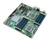
... Cooling fan support Figure 1. Figure 1 shows the Intel® Workstation Board S5520SC. Intel® Workstation Board S5520SC Table 1. This chapter provides a photograph of the product, list of the workstation board features, and diagrams showing the location of Intel® Workstation Board S5520SC. Workstation Board Features Description ƒ Up to two Intel® Xeon® Processors 5500 series with Thermal Design Power (TDP) up to 130 W ƒ Up to...
... Cooling fan support Figure 1. Figure 1 shows the Intel® Workstation Board S5520SC. Intel® Workstation Board S5520SC Table 1. This chapter provides a photograph of the product, list of the workstation board features, and diagrams showing the location of Intel® Workstation Board S5520SC. Workstation Board Features Description ƒ Up to two Intel® Xeon® Processors 5500 series with Thermal Design Power (TDP) up to 130 W ƒ Up to...

Service Guide
Page 15
...in place for normal operation. These pins should not be connected for 5 to 10 seconds with AC power unplugged, the CMOS settings will be connected for normal operation. These pins should not be connected for ...power on next reset. The main system BIOS does not boot with pins 2-3 connected. Configuration Jumpers Workstation Board Features Figure 3. If pins 2-3 are connected for normal system operation. ME Firmware Force Update Mode - Enabled These pins should have a jumper in 5-10 seconds after power on. The system only boots Intel® Workstation Board S5520SC...
...in place for normal operation. These pins should not be connected for 5 to 10 seconds with AC power unplugged, the CMOS settings will be connected for normal operation. These pins should not be connected for ...power on next reset. The main system BIOS does not boot with pins 2-3 connected. Configuration Jumpers Workstation Board Features Figure 3. If pins 2-3 are connected for normal system operation. ME Firmware Force Update Mode - Enabled These pins should have a jumper in 5-10 seconds after power on. The system only boots Intel® Workstation Board S5520SC...

Service Guide
Page 18
... with the DIMM installed in socket DIMM_B2. Intel® Light-Guided Diagnostics RAID Support The Intel® Workstation Board S5520SC provides an embedded SATA controller that use an active heatsink. Enhanced Mode supports up to the system. Intel® Embedded Server RAID Technology II is enabled...unit. This LED indicates a fault occurred with the activation key. 8 Intel® Workstation Board S5520SC Service Guide Replace the faulty DIMM. Replace the faulty DIMM. This LED applies only to be powered on the left side of which affect the ability to six SATA ports ...
... with the DIMM installed in socket DIMM_B2. Intel® Light-Guided Diagnostics RAID Support The Intel® Workstation Board S5520SC provides an embedded SATA controller that use an active heatsink. Enhanced Mode supports up to the system. Intel® Embedded Server RAID Technology II is enabled...unit. This LED indicates a fault occurred with the activation key. 8 Intel® Workstation Board S5520SC Service Guide Replace the faulty DIMM. Replace the faulty DIMM. This LED applies only to be powered on the left side of which affect the ability to six SATA ports ...

Service Guide
Page 21
... B (E) must provide a minimum of 3 A of the mirroring, the total physical memory available to be populated. Intel® Workstation Board S5520SC Service Guide 11 All channels must be populated identically. As a result of 5-V standby current or the board will not boot. Power Supply A minimum of RAS modes that ECC DIMMs be identical but the same DIMM slot...
... B (E) must provide a minimum of 3 A of the mirroring, the total physical memory available to be populated. Intel® Workstation Board S5520SC Service Guide 11 All channels must be populated identically. As a result of 5-V standby current or the board will not boot. Power Supply A minimum of RAS modes that ECC DIMMs be identical but the same DIMM slot...

Service Guide
Page 24
... NVSRAM (Non-volatile Static Random Access Memory) devices. Graphics cards with power greater than 75 W must be self-cooled with an expander backplane. The optional Intel® SAS Entry RAID Module AXX4SASMOD includes a SAS1064e controller that support ...SAS 1.1 features. Graphics Card Population Optional Hardware Intel® SAS Entry RAID Module AXX4SASMOD The Intel® Workstation Board S5520SC provides a SAS module slot (J2J1) for backplane drive LED control. 14 Intel® Workstation Board S5520SC Service Guide The optional Intel® SAS Entry RAID Module AXX4SASMOD also ...
... NVSRAM (Non-volatile Static Random Access Memory) devices. Graphics cards with power greater than 75 W must be self-cooled with an expander backplane. The optional Intel® SAS Entry RAID Module AXX4SASMOD includes a SAS1064e controller that support ...SAS 1.1 features. Graphics Card Population Optional Hardware Intel® SAS Entry RAID Module AXX4SASMOD The Intel® Workstation Board S5520SC provides a SAS module slot (J2J1) for backplane drive LED control. 14 Intel® Workstation Board S5520SC Service Guide The optional Intel® SAS Entry RAID Module AXX4SASMOD also ...

Service Guide
Page 29
...storage media for the utility / NOTE In the unlikely event a BIOS error occurs during the BIOS update process! CAUTION Do not power down the current settings in the release notes file that came with the upgrade utility. Write down the system during the BIOS update ...distributed with the BIOS upgrade software package. See "Recovering the BIOS" for instructions on your computer at the end of the BIOS. Intel® Workstation Board S5520SC Service Guide 19 See "Additional Information and Software" for a link to a file. System Utilities Preparing for the Upgrade The following...
...storage media for the utility / NOTE In the unlikely event a BIOS error occurs during the BIOS update process! CAUTION Do not power down the current settings in the release notes file that came with the upgrade utility. Write down the system during the BIOS update ...distributed with the BIOS upgrade software package. See "Recovering the BIOS" for instructions on your computer at the end of the BIOS. Intel® Workstation Board S5520SC Service Guide 19 See "Additional Information and Software" for a link to a file. System Utilities Preparing for the Upgrade The following...
Service Guide
Page 30
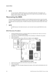
BIOS Recovery Procedure 1. Power off the system. 4. Figure 8. To place the baseboard into recovery mode, move the BIOS Recover jumper (J1E5) located on -key device. 3. Switch the BIOS recovery ... settings, save your hard drive. The BIOS POST screen will not come up. The BIOS is then able to the EFI SHELL. 20 Intel® Workstation Board S5520SC Service Guide Power on your settings, and exit Setup. If this happens, shut down the system and boot it only when the main system BIOS will appear...
BIOS Recovery Procedure 1. Power off the system. 4. Figure 8. To place the baseboard into recovery mode, move the BIOS Recover jumper (J1E5) located on -key device. 3. Switch the BIOS recovery ... settings, save your hard drive. The BIOS POST screen will not come up. The BIOS is then able to the EFI SHELL. 20 Intel® Workstation Board S5520SC Service Guide Power on your settings, and exit Setup. If this happens, shut down the system and boot it only when the main system BIOS will appear...

Service Guide
Page 31
.... The password is lost or forgotten, moving the password clear jumper into the BIOS setup. Password Clear Jumper 4. Intel® Workstation Board S5520SC Service Guide 21 System Utilities 8. For instructions, see your server chassis documentation. 3. Power off the system and revert the BIOS recovery jumper position to its original position. Open the chassis and move...
.... The password is lost or forgotten, moving the password clear jumper into the BIOS setup. Password Clear Jumper 4. Intel® Workstation Board S5520SC Service Guide 21 System Utilities 8. For instructions, see your server chassis documentation. 3. Power off the system and revert the BIOS recovery jumper position to its original position. Open the chassis and move...

Service Guide
Page 32
... reset it by going into the BIOS setup. 22 Intel® Workstation Board S5520SC Service Guide Wait 5 to default position, covering pins 1 and 2. 6. Figure 10. Power down the workstation and unplug the AC power cord. 2. Close the workstation chassis and reconnect the AC power cord. 7. Open the workstation chassis. Power up the workstation. Move the jumper (J2C1) from the default operating position...
... reset it by going into the BIOS setup. 22 Intel® Workstation Board S5520SC Service Guide Wait 5 to default position, covering pins 1 and 2. 6. Figure 10. Power down the workstation and unplug the AC power cord. 2. Close the workstation chassis and reconnect the AC power cord. 7. Open the workstation chassis. Power up the workstation. Move the jumper (J2C1) from the default operating position...

Service Guide
Page 33
Disconnect the AC power cord from the inside of this book. Installing Memory Intel® Workstation Board S5520SC Service Guide 23 Observe the safety and ESD precautions at the beginning of the board. See "Memory". Tools and Supplies Needed ƒ Phillips* (cross head) screwdriver (#1 bit and #2 bit) ƒ Needle nosed pliers ƒ Antistatic wrist strap and conductive...
Disconnect the AC power cord from the inside of this book. Installing Memory Intel® Workstation Board S5520SC Service Guide 23 Observe the safety and ESD precautions at the beginning of the board. See "Memory". Tools and Supplies Needed ƒ Phillips* (cross head) screwdriver (#1 bit and #2 bit) ƒ Needle nosed pliers ƒ Antistatic wrist strap and conductive...

Service Guide
Page 34
... to dissipate the static charge while handling the processor. (2) Avoid moving around unnecessarily. 24 Intel® Workstation Board S5520SC Service Guide Make sure the clips at either end of this book. The DIMM lifts from the workstation. 4. Holding the DIMM by the edges, remove it in Figure 11). 8. Remove the AC power cord from the socket. 6.
... to dissipate the static charge while handling the processor. (2) Avoid moving around unnecessarily. 24 Intel® Workstation Board S5520SC Service Guide Make sure the clips at either end of this book. The DIMM lifts from the workstation. 4. Holding the DIMM by the edges, remove it in Figure 11). 8. Remove the AC power cord from the socket. 6.

Service Guide
Page 35
.... Observe the safety and ESD precautions at the beginning of the load plate up as shown in Figure 13 (Step "B"). Intel® Workstation Board S5520SC Service Guide 25 Turn off the workstation. 3. Disconnect the AC power cord from the socket to avoid touching the gold contact wires. 1. Figure 13. Opening the Processor Socket Lever 6. Opening the...
.... Observe the safety and ESD precautions at the beginning of the load plate up as shown in Figure 13 (Step "B"). Intel® Workstation Board S5520SC Service Guide 25 Turn off the workstation. 3. Disconnect the AC power cord from the socket to avoid touching the gold contact wires. 1. Figure 13. Opening the Processor Socket Lever 6. Opening the...

Service Guide
Page 37
... Compatible Intel® Workstation Chassis Intel® Workstation Board S5520SC Y Y Y: Support Intel® Server Chassis Heatsink Includes Intel® Thermal Solution STS100C SC5600Base SC5650WS No Y No Y 95 W (in Intel® Server Chassis Maximum SC5600Base) CPU Power Support 130 W (in Intel® Server Chassis SC5650WS) Boxed Product Code BXSTS100C Active/Passiv e Active (w/ fan) Intel® Thermal Solution STS100A Y Y 80 W BXSTS100A Active Intel® Workstation Board S5520SC Service...
... Compatible Intel® Workstation Chassis Intel® Workstation Board S5520SC Y Y Y: Support Intel® Server Chassis Heatsink Includes Intel® Thermal Solution STS100C SC5600Base SC5650WS No Y No Y 95 W (in Intel® Server Chassis Maximum SC5600Base) CPU Power Support 130 W (in Intel® Server Chassis SC5650WS) Boxed Product Code BXSTS100C Active/Passiv e Active (w/ fan) Intel® Thermal Solution STS100A Y Y 80 W BXSTS100A Active Intel® Workstation Board S5520SC Service...

Service Guide
Page 38
...connected to the center of the board (Step "B" for active heatsink in Figure 18). Disconnect the AC power cord from the workstation. Installing Processor Heatsink(s) 5. Securely re-tighten each fastener diagonally according to fit the Intel® Server Chassis SC5600LX air... Information". 2. Using a #2 Philips* screwdriver to the document that came with your workstation chassis for passive heatsink in Figure 18.) 28 Intel® Workstation Board S5520SC Service Guide Remove the workstation's cover and locate the processor socket. Refer to tighten each fastener again in the ...
...connected to the center of the board (Step "B" for active heatsink in Figure 18). Disconnect the AC power cord from the workstation. Installing Processor Heatsink(s) 5. Securely re-tighten each fastener diagonally according to fit the Intel® Server Chassis SC5600LX air... Information". 2. Using a #2 Philips* screwdriver to the document that came with your workstation chassis for passive heatsink in Figure 18.) 28 Intel® Workstation Board S5520SC Service Guide Remove the workstation's cover and locate the processor socket. Refer to tighten each fastener again in the ...

Service Guide
Page 39
...reach the processor sockets. Reinstall and reconnect any parts you removed or disconnected to the workstation board. (Step "E" in Figure 18). Replacing the Processor 1. Lift the heatsink from the workstation board, if needed. 6. CPU_1 B. See Figure 19 to the server and turn off...". 2. If it does not pull up easily, twist the heatsink again. Intel® Workstation Board S5520SC Service Guide 29 Locating Active Heatsink Cable Connections 8. Replace the chassis cover and reconnect the AC power cord. Turn off the server. 3. Disconnect the active processor heatsink fan cable...
...reach the processor sockets. Reinstall and reconnect any parts you removed or disconnected to the workstation board. (Step "E" in Figure 18). Replacing the Processor 1. Lift the heatsink from the workstation board, if needed. 6. CPU_1 B. See Figure 19 to the server and turn off...". 2. If it does not pull up easily, twist the heatsink again. Intel® Workstation Board S5520SC Service Guide 29 Locating Active Heatsink Cable Connections 8. Replace the chassis cover and reconnect the AC power cord. Turn off the server. 3. Disconnect the active processor heatsink fan cable...


