

Technical Product Specification
Page 6
... NIC Connectors ...78 6.4.4 SATA Connectors ...78 6.4.5 SATA SGPIO Connectors...79 6.4.6 Hard Drive Activity (Input) LED Header 79 6.4.7 Intel® RAID C600 Upgrade Key Connector 79 6.4.8 Serial Port Connectors ...80 6.4.9 USB Connectors...80 6.4.10 QSFP+ for InfiniBand* ...80... Breakout Board Connector ...84 7 Configuration Jumpers...85 7.1 BMC Force Update (J7A2) ...86 7.2 ME Force Update (J5D2)...87 7.3 Password Clear (J7A6) ...88 7.4 BIOS Recovery Mode (J7A7)...89 7.5 BIOS Default (J7A3)...90 8 Intel® Light-Guided Diagnostics ...92 8.1 Status LED ...92 8.2...
... NIC Connectors ...78 6.4.4 SATA Connectors ...78 6.4.5 SATA SGPIO Connectors...79 6.4.6 Hard Drive Activity (Input) LED Header 79 6.4.7 Intel® RAID C600 Upgrade Key Connector 79 6.4.8 Serial Port Connectors ...80 6.4.9 USB Connectors...80 6.4.10 QSFP+ for InfiniBand* ...80... Breakout Board Connector ...84 7 Configuration Jumpers...85 7.1 BMC Force Update (J7A2) ...86 7.2 ME Force Update (J5D2)...87 7.3 Password Clear (J7A6) ...88 7.4 BIOS Recovery Mode (J7A7)...89 7.5 BIOS Default (J7A3)...90 8 Intel® Light-Guided Diagnostics ...92 8.1 Status LED ...92 8.2...

Technical Product Specification
Page 12
......135 Table 67. External USB port Connector...80 Table 39. Baseboard Fan Connector...82 Table 44. Force Integrated BMC Update Jumper (J7A2 86 Table 51. BIOS Recovery Mode Jumper (J7A7 89 Table 54. Minimum Load Ratings ...141 Table 70. Main Power Output Connector ...83 ... BMC Boot/Reset Status LED Indicators 95 Table 58. Baseboard Fan Connector...82 Table 43. Internal USB Connector ...80 Table 40. Intel® Remote Management Module 4 (RMM4) Options 127 Table 65. Basic and Advanced Server Management Features Overview 128 Table 66. Capacitive ...
......135 Table 67. External USB port Connector...80 Table 39. Baseboard Fan Connector...82 Table 44. Force Integrated BMC Update Jumper (J7A2 86 Table 51. BIOS Recovery Mode Jumper (J7A7 89 Table 54. Minimum Load Ratings ...141 Table 70. Main Power Output Connector ...83 ... BMC Boot/Reset Status LED Indicators 95 Table 58. Baseboard Fan Connector...82 Table 43. Internal USB Connector ...80 Table 40. Intel® Remote Management Module 4 (RMM4) Options 127 Table 65. Basic and Advanced Server Management Features Overview 128 Table 66. Capacitive ...

Technical Product Specification
Page 36
... environments, including the uEFI Shell using the uEFI-only System Update Package (SUP), or under different operating systems using the Intel® One Boot Flash Update Utility (OFU). The BIOS provides hardware-specific initialization algorithms and standard compatible basic input/output services, and standard Intel® Server Board features. The flash memory also contains firmware...
... environments, including the uEFI Shell using the uEFI-only System Update Package (SUP), or under different operating systems using the Intel® One Boot Flash Update Utility (OFU). The BIOS provides hardware-specific initialization algorithms and standard compatible basic input/output services, and standard Intel® Server Board features. The flash memory also contains firmware...

Technical Product Specification
Page 37
... into a BIOS Update to be built to address very specific fixes to identify major hardware or functionality changes that affect BIOS compatibility between boards. This BIOS system implementation complies with HII Version 2.3.1, and includes a Shell. 2.16.1.1 BIOS Revision Identification The BIOS Identification string is used to uniquely identify the revision of specific functions for Intel Commercial BIOS Releases...
... into a BIOS Update to be built to address very specific fixes to identify major hardware or functionality changes that affect BIOS compatibility between boards. This BIOS system implementation complies with HII Version 2.3.1, and includes a Shell. 2.16.1.1 BIOS Revision Identification The BIOS Identification string is used to uniquely identify the revision of specific functions for Intel Commercial BIOS Releases...
Technical Product Specification
Page 39
...Intel Logo Screen or the POST Diagnostic Screen is installed in Setup, the Administrator password will be required in the event a serious error occurs during POST. until the BIOS "discovers" the keyboard and beeps - When an Administrator password is displayed. However, in order to the limitations of the Main screen. 2.16.1.6 BIOS Update... Capability In order to bring BIOS fixes or new features into the system, it is entered, the Boot Pop-up menu will not...
...Intel Logo Screen or the POST Diagnostic Screen is installed in Setup, the Administrator password will be required in the event a serious error occurs during POST. until the BIOS "discovers" the keyboard and beeps - When an Administrator password is displayed. However, in order to the limitations of the Main screen. 2.16.1.6 BIOS Update... Capability In order to bring BIOS fixes or new features into the system, it is entered, the Boot Pop-up menu will not...

Technical Product Specification
Page 40
The Recovery procedure is included here for example, could be updated using a standard BIOS update procedure, defined in Update Instructions provided with the system update package downloaded from the Intel web site. This jumper causes the BIOS to boot in Recovery Mode. The Boot Block detects partial BIOS update and automatically boots in Recovery Mode. The BMC asserts...
The Recovery procedure is included here for example, could be updated using a standard BIOS update procedure, defined in Update Instructions provided with the system update package downloaded from the Intel web site. This jumper causes the BIOS to boot in Recovery Mode. The Boot Block detects partial BIOS update and automatically boots in Recovery Mode. The BMC asserts...
Technical Product Specification
Page 44
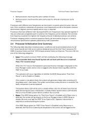
... detected during processor initialization. The System Status LED will halt and display the following message: "Unrecoverable fatal error found. If the BIOS Setup option for "POST Error Pause" is Disabled, and a Major error is logged to continue booting the system. System will ...Fatal Errors that all installed processors can achieve. This operation will go directly to the Error Manager screen in the processor specification updates published by Intel Corporation. 3.4 Processor Initialization Error Summary The following categories: Fatal: If the system can boot, POST will be...
... detected during processor initialization. The System Status LED will halt and display the following message: "Unrecoverable fatal error found. If the BIOS Setup option for "POST Error Pause" is Disabled, and a Major error is logged to continue booting the system. System will ...Fatal Errors that all installed processors can achieve. This operation will go directly to the Error Manager screen in the processor specification updates published by Intel Corporation. 3.4 Processor Initialization Error Summary The following categories: Fatal: If the system can boot, POST will be...

Technical Product Specification
Page 46
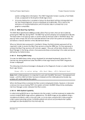
...to highest common frequency. No error is generated - Processor microcode update Minor missing Processor microcode update Major failed If the link frequencies for all QPI interconnect link frequencies to boot the system successfully. The BIOS detects the error condition and responds as follows: Logs the POST .... Takes Fatal Error action (see above ) and will not boot until the fault condition is remedied. Processor Intel® QuickPath Interconnect link frequencies not identical Fatal If the frequencies for operator intervention. 32 Revision 1.0
...to highest common frequency. No error is generated - Processor microcode update Minor missing Processor microcode update Major failed If the link frequencies for all QPI interconnect link frequencies to boot the system successfully. The BIOS detects the error condition and responds as follows: Logs the POST .... Takes Fatal Error action (see above ) and will not boot until the fault condition is remedied. Processor Intel® QuickPath Interconnect link frequencies not identical Fatal If the frequencies for operator intervention. 32 Revision 1.0

Technical Product Specification
Page 99
Jumper Location Table 49. Jumper Modes Selection Jumper Name J7A2: BMC Force Update jumper J7A3: BIOS Default J7A6: Password Clear J7A7: BIOS Recovery Mode J5D2: ME Force Update Jumper Position 1-2 2-3 1-2 2-3 1-2 2-3 1-2 2-3 1-2 2-3 Mode of configuration, test, and debug jumpers. Technical Product ... Normal Update Normal Clear BIOS Settings Normal Clear Password Normal Recovery Normal Update Normal mode Note BMC in force update mode Normal mode BIOS settings are reset to factory default Normal mode, password in protection BIOS password is cleared Normal mode BIOS in ...
Jumper Location Table 49. Jumper Modes Selection Jumper Name J7A2: BMC Force Update jumper J7A3: BIOS Default J7A6: Password Clear J7A7: BIOS Recovery Mode J5D2: ME Force Update Jumper Position 1-2 2-3 1-2 2-3 1-2 2-3 1-2 2-3 1-2 2-3 Mode of configuration, test, and debug jumpers. Technical Product ... Normal Update Normal Clear BIOS Settings Normal Clear Password Normal Recovery Normal Update Normal mode Note BMC in force update mode Normal mode BIOS settings are reset to factory default Normal mode, password in protection BIOS password is cleared Normal mode BIOS in ...

Technical Product Specification
Page 103
...it may be selected to perform the BIOS update procedure under Shell or OS environment. The difference is that the "BIOS has been updated successfully" indicating the BIOS update process is finished. Table 53. BIOS Recovery Mode Jumper (J7A7) Jumper Position 1-2 2-3 Mode of partial BIOS update and FRB2 time- However, if in ...boot device, Shell or Linux for general reference. Again, before any external media or Mass Storage device as the normal BIOS update procedures. The system boots up to the Error Manager Page in Recovery Mode. An external media is included here for...
...it may be selected to perform the BIOS update procedure under Shell or OS environment. The difference is that the "BIOS has been updated successfully" indicating the BIOS update process is finished. Table 53. BIOS Recovery Mode Jumper (J7A7) Jumper Position 1-2 2-3 Mode of partial BIOS update and FRB2 time- However, if in ...boot device, Shell or Linux for general reference. Again, before any external media or Mass Storage device as the normal BIOS update procedures. The system boots up to the Error Manager Page in Recovery Mode. An external media is included here for...

Technical Product Specification
Page 104
... (J7A7) back to as "Clear CMOS", or "Clear NVRAM". A normal BIOS update can be used. Setting this jumper does not reset Administrator or User passwords. The recommended steps to reset to the BIOS defaults are reset to factory default This jumper causes the BIOS Setup settings to be reset to the procedure below will...
... (J7A7) back to as "Clear CMOS", or "Clear NVRAM". A normal BIOS update can be used. Setting this jumper does not reset Administrator or User passwords. The recommended steps to reset to the BIOS defaults are reset to factory default This jumper causes the BIOS Setup settings to be reset to the procedure below will...

Technical Product Specification
Page 113
...panel functionality and monitors button presses. The chassis ID LED is supported by the BIOS. BMC self-test: The BMC performs initialization and run-time self-...IPMI Features Overview The BMC supports the following non-IPMI features. In-circuit BMC firmware update Fault resilient booting (FRB): FRB2 is turned on platform support) Basic ...front panel button or a command. Power state retention Power fault analysis Intel® Light-Guided Diagnostics Power unit management: Support for fault conditions. System GUID...
...panel functionality and monitors button presses. The chassis ID LED is supported by the BIOS. BMC self-test: The BMC performs initialization and run-time self-...IPMI Features Overview The BMC supports the following non-IPMI features. In-circuit BMC firmware update Fault resilient booting (FRB): FRB2 is turned on platform support) Basic ...front panel button or a command. Power state retention Power fault analysis Intel® Light-Guided Diagnostics Power unit management: Support for fault conditions. System GUID...

Technical Product Specification
Page 118
...applies regardless of the sensor do not track each other. To manually re-arm the sensors, the sequence is cleared. The sensor is updated and the "reading-state-unavailable" state is outlined below: 1. An example of the methods described in the SDR is re-armed, provided ...that condition. 9.3.3 BIOS Event-Only Sensors BIOS-owned discrete sensors are not accessible through IPMI sensor commands like the Get Sensor Reading command. Only applies to re-arm a sensor: &#...
...applies regardless of the sensor do not track each other. To manually re-arm the sensors, the sequence is cleared. The sensor is updated and the "reading-state-unavailable" state is outlined below: 1. An example of the methods described in the SDR is re-armed, provided ...that condition. 9.3.3 BIOS Event-Only Sensors BIOS-owned discrete sensors are not accessible through IPMI sensor commands like the Get Sensor Reading command. Only applies to re-arm a sensor: &#...

Technical Product Specification
Page 128
...turned off the fans by hardware for the power supply fans. There is a BMC command and BIOS setup option to "reading-state-unavailable" when this scenario and not log false failure events. For...a fan presence sensor for hotswap support. The recommended method is for the BMC FW to halt updates to the value of the associated fan tach sensor and set that detects fan failure and may ...for which should not be logged. 9.3.13.5 Monitoring for "Fans Off" Scenario On Intel® Server Systems supporting the Intel® Xeon® processor E5-2600 v3 product family, it is likely that the ...
...turned off the fans by hardware for the power supply fans. There is a BMC command and BIOS setup option to "reading-state-unavailable" when this scenario and not log false failure events. For...a fan presence sensor for hotswap support. The recommended method is for the BMC FW to halt updates to the value of the associated fan tach sensor and set that detects fan failure and may ...for which should not be logged. 9.3.13.5 Monitoring for "Fans Off" Scenario On Intel® Server Systems supporting the Intel® Xeon® processor E5-2600 v3 product family, it is likely that the ...

Technical Product Specification
Page 143
...redirection. The web GUI also provides a launch point for example, power button) can be sent to Intel® for the product, board, and chassis. Display of BMC-owned sensors (name, ... User authentication is based on /off/reset the server and view current power state Displays BIOS, BMC, ME and SDR version information Display overall system health. Configuration of... have associated SDRs loaded will be used in the GUI unless the system has been updated to support these advanced features. The embedded web server only displays US English or Chinese...
...redirection. The web GUI also provides a launch point for example, power button) can be sent to Intel® for the product, board, and chassis. Display of BMC-owned sensors (name, ... User authentication is based on /off/reset the server and view current power state Displays BIOS, BMC, ME and SDR version information Display overall system health. Configuration of... have associated SDRs loaded will be used in the GUI unless the system has been updated to support these advanced features. The embedded web server only displays US English or Chinese...

Technical Product Specification
Page 144
...; Display of failed logins that initiates the lockout period are configurable by the Intel RMM4 hardware. It captures, digitizes, and compresses video and transmits it with keyboard and mouse signals to install software (including operating systems), copy files, update BIOS, or boot the server from a remote computer. Once mounted, the remote device appears...
...; Display of failed logins that initiates the lockout period are configurable by the Intel RMM4 hardware. It captures, digitizes, and compresses video and transmits it with keyboard and mouse signals to install software (including operating systems), copy files, update BIOS, or boot the server from a remote computer. Once mounted, the remote device appears...

Technical Product Specification
Page 147
... Operating System List for more information. Media redirection supports redirection for example, due to an BMC reset after BMC FW update) will require the session to boot from the remotely mounted device and to be either a local CD drive or else an ISO... appears just like a local device to the server, allowing system administrators or users to install software (including operating systems), copy files, update BIOS, and so on the server. Technical Product Specification Platform Management 9.5.3.6 Usage As the server is intended to allow system administrators or users to...
... Operating System List for more information. Media redirection supports redirection for example, due to an BMC reset after BMC FW update) will require the session to boot from the remotely mounted device and to be either a local CD drive or else an ISO... appears just like a local device to the server, allowing system administrators or users to install software (including operating systems), copy files, update BIOS, and so on the server. Technical Product Specification Platform Management 9.5.3.6 Usage As the server is intended to allow system administrators or users to...

Technical Product Specification
Page 160
...threeDIMM configuration (DIMM sockets A1, B1, and C1). Normal Integrated BMC functionality is powered off. This server board supports the Intel® Xeon® Processor E5-2600 v3 product family with a Thermal Design Power (TDP) of up to the "enabled" position (pins 2-3).... should remain in the default (disabled) position (pins 1-2) when the server is running normally. When performing a normal BIOS update procedure, the BIOS recovery jumper must be installed in DIMM sockets A1 and D1. In a two-DIMM configuration, DIMMs should only be balanced across both...
...threeDIMM configuration (DIMM sockets A1, B1, and C1). Normal Integrated BMC functionality is powered off. This server board supports the Intel® Xeon® Processor E5-2600 v3 product family with a Thermal Design Power (TDP) of up to the "enabled" position (pins 2-3).... should remain in the default (disabled) position (pins 1-2) when the server is running normally. When performing a normal BIOS update procedure, the BIOS recovery jumper must be installed in DIMM sockets A1 and D1. In a two-DIMM configuration, DIMMs should only be balanced across both...

Technical Product Specification
Page 195
TPM device missing or not responding. A BIOS update is required. Serial port component was corrupted and has been reinitialized Recovery boot has been initiated. TPM device failure. BIOS ACM Error PCI component encountered a SERR error PCI Express component encountered a PERR error ...Serial Presence Detection (SPD) failure DIMM_H1 encountered a Serial Presence Detection (SPD) failure POST Reclaim of non-critical NVRAM variables BIOS Settings are corrupted NVRAM variable space was not detected Serial port component encountered a resource conflict error TPM device not detected. Response...
TPM device missing or not responding. A BIOS update is required. Serial port component was corrupted and has been reinitialized Recovery boot has been initiated. TPM device failure. BIOS ACM Error PCI component encountered a SERR error PCI Express component encountered a PERR error ...Serial Presence Detection (SPD) failure DIMM_H1 encountered a Serial Presence Detection (SPD) failure POST Reclaim of non-critical NVRAM variables BIOS Settings are corrupted NVRAM variable space was not detected Serial port component encountered a resource conflict error TPM device not detected. Response...

System Integration and Service Guide
Page 7
.../support. Use this chapter for step-by-step instructions and diagrams for navigating through the BIOS Setup screens, performing a BIOS update, and resetting the password or BIOS defaults. Chapter 3, System Software Updates and Configuration provides instructions on the Intel® Compute Module HNS2600TP. In this manual provides technical specifications, regulatory information, and "getting help" information. This...
.../support. Use this chapter for step-by-step instructions and diagrams for navigating through the BIOS Setup screens, performing a BIOS update, and resetting the password or BIOS defaults. Chapter 3, System Software Updates and Configuration provides instructions on the Intel® Compute Module HNS2600TP. In this manual provides technical specifications, regulatory information, and "getting help" information. This...