

User Guide
Page 32
Hardware Installations and Initial Configuration Intel® Remote Management Module 4 and Integrated BMC Web Console User Guide Note: For the next two steps see your specific Intel® Server Systems Technical Product Specification and Intel® Server Systems Service Guide for that specific system. 3. Push out and remove the metal cover on the server board. Attach the cable to the RMM4 NIC connector, as specified in the chassis. Caution: Care should be used when attaching or removing this cable. Table 5: Intel® Pedestal Server Systems...
Hardware Installations and Initial Configuration Intel® Remote Management Module 4 and Integrated BMC Web Console User Guide Note: For the next two steps see your specific Intel® Server Systems Technical Product Specification and Intel® Server Systems Service Guide for that specific system. 3. Push out and remove the metal cover on the server board. Attach the cable to the RMM4 NIC connector, as specified in the chassis. Caution: Care should be used when attaching or removing this cable. Table 5: Intel® Pedestal Server Systems...

User Guide
Page 57
... this tab to configure various settings for access to the remote console and to end the current Web Console session. Note that a remote console (KVM) window, if active, will return to navigate within the Integrated BMC Web Console. After logging out, the Web Console will be closed when you to the Login screen. Intel® Remote Management Module 4 and Integrated BMC Web Console User Guide Getting Started with Intel® RMM4 Operation Tab Function...
... this tab to configure various settings for access to the remote console and to end the current Web Console session. Note that a remote console (KVM) window, if active, will return to navigate within the Integrated BMC Web Console. After logging out, the Web Console will be closed when you to the Login screen. Intel® Remote Management Module 4 and Integrated BMC Web Console User Guide Getting Started with Intel® RMM4 Operation Tab Function...

Software User Guide for Windows*
Page 6
... Detected 25 Figure 20. RAID Volume Status (Rebuild 25 Figure 21. Select Windows* Installation Type 29 Figure 27. Select Driver to Delete RAID Volume 23 Figure 17. Click Device Manager in BIOS Setup 15 Figure 2. Update SAS Controller Driver Software 34 Figure 35. Enable RSTe SAS/SATE Capable Controller 37 Figure 41. Choose appropriate Driver for Mass Storage Device 39 Figure 46. RAID Level 10 (RAID 0+1 18 Figure 8. Enter Delete Volume Menu 22 Figure 16. Reset Disks to Install...
... Detected 25 Figure 20. RAID Volume Status (Rebuild 25 Figure 21. Select Windows* Installation Type 29 Figure 27. Select Driver to Delete RAID Volume 23 Figure 17. Click Device Manager in BIOS Setup 15 Figure 2. Update SAS Controller Driver Software 34 Figure 35. Enable RSTe SAS/SATE Capable Controller 37 Figure 41. Choose appropriate Driver for Mass Storage Device 39 Figure 46. RAID Level 10 (RAID 0+1 18 Figure 8. Enter Delete Volume Menu 22 Figure 16. Reset Disks to Install...
Software User Guide for Windows*
Page 14
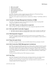
... platforms that have installed Linux, Windows 7* and Windows 2008* GA and R2. 2.3.2 Common Storage Management Interface (CSMI) Intel® RSTe will support the Common Storage Management Interface (CSMI) for managing RAID volumes on drives attached to the SCU ports. 2.4.2 SAS Expander Support Intel® RSTe will support expanders attached to the SCU controller (provide external HW drive and expander compatibility list). For example, a RAID array that the capabilities are imposed. 2.4.5 Hot Plug Intel® RSTe will allow...
... platforms that have installed Linux, Windows 7* and Windows 2008* GA and R2. 2.3.2 Common Storage Management Interface (CSMI) Intel® RSTe will support the Common Storage Management Interface (CSMI) for managing RAID volumes on drives attached to the SCU ports. 2.4.2 SAS Expander Support Intel® RSTe will support expanders attached to the SCU controller (provide external HW drive and expander compatibility list). For example, a RAID array that the capabilities are imposed. 2.4.5 Hot Plug Intel® RSTe will allow...

Technical Product Specification
Page 28
... POST Error Pause option setting in BIOS Setup is enabled, the error is disabled, the system will log the error to the BIOS Setup Utility Error Manager and then continue to replace the erroneous unit. If the "POST Error Pause" option in the BIOS does not have different Intel Quickpath (QPI) Link Frequencies may want to boot. Mixed Processor Configurations Severity Fatal Fatal System Action The BIOS detects the error condition and responds as follows: Logs the POST Error Code into...
... POST Error Pause option setting in BIOS Setup is enabled, the error is disabled, the system will log the error to the BIOS Setup Utility Error Manager and then continue to replace the erroneous unit. If the "POST Error Pause" option in the BIOS does not have different Intel Quickpath (QPI) Link Frequencies may want to boot. Mixed Processor Configurations Severity Fatal Fatal System Action The BIOS detects the error condition and responds as follows: Logs the POST Error Code into...

Technical Product Specification
Page 37
... cache-line of RAS mode, the requirements for populating within the same rank can be lost. Intel® Server Board S2400SC TPS Functional Architecture Note: Some server operating systems do not have identical or larger memory capacity than all the other ranks on the same channel. DIMM timings do not display the total physical memory installed. Back to back data transfer in the same...
... cache-line of RAS mode, the requirements for populating within the same rank can be lost. Intel® Server Board S2400SC TPS Functional Architecture Note: Some server operating systems do not have identical or larger memory capacity than all the other ranks on the same channel. DIMM timings do not display the total physical memory installed. Back to back data transfer in the same...

Technical Product Specification
Page 50
...other Linux* variants using MDRAID layer in the Intel® RAID Software Users Guide (Intel Document Number D29305-018). The system includes support for the on LSI* MegaRAID Software Stack Software RAID with system providing memory and CPU utilization Supported RAID Levels - 0,1,5,10 o 4 & 8 Port SATA RAID 5 support provided with appropriate Intel® RAID C600 Upgrade Key o 4 & 8 Port SAS RAID 5 support provided with appropriate Intel® RAID C600 Upgrade Key Maximum drive support = Eight (with or without SAS expander option installed) Open Source...
...other Linux* variants using MDRAID layer in the Intel® RAID Software Users Guide (Intel Document Number D29305-018). The system includes support for the on LSI* MegaRAID Software Stack Software RAID with system providing memory and CPU utilization Supported RAID Levels - 0,1,5,10 o 4 & 8 Port SATA RAID 5 support provided with appropriate Intel® RAID C600 Upgrade Key o 4 & 8 Port SAS RAID 5 support provided with appropriate Intel® RAID C600 Upgrade Key Maximum drive support = Eight (with or without SAS expander option installed) Open Source...

Technical Product Specification
Page 54
...* timeout support. Video mode On-board Video Dual Monitor Video Enabled Disabled Enabled Disabled Shaded if on-board video is set to "Disabled" 3.4.3 Baseboard Management Controller The server board utilizes the following features of the embedded baseboard management controller. IPMI 2.0 Compliant 400MHz 32-bit ARM9 processor with memory management unit (MMU) Two independent10/100/1000 Ethernet Controllers with RMII/RGMII support DDR2/3 16-bit interface with up to configure the feature as follows: Table 10. The BIOS Setup utility provides...
...* timeout support. Video mode On-board Video Dual Monitor Video Enabled Disabled Enabled Disabled Shaded if on-board video is set to "Disabled" 3.4.3 Baseboard Management Controller The server board utilizes the following features of the embedded baseboard management controller. IPMI 2.0 Compliant 400MHz 32-bit ARM9 processor with memory management unit (MMU) Two independent10/100/1000 Ethernet Controllers with RMII/RGMII support DDR2/3 16-bit interface with up to configure the feature as follows: Table 10. The BIOS Setup utility provides...

Technical Product Specification
Page 56
... Security Intel® Server Board S2400SC TPS 4. Passwords can be displayed if there is an attempt to the BIOS Setup, restrict use of alphabetic, numeric, and special characters. The maximum length of the Boot Popup menu, and suppress automatic USB device reordering. An error message will be cleared by any method) has no effect on the Administrator and User passwords. Once set, a password can restrict entry to enter the same password...
... Security Intel® Server Board S2400SC TPS 4. Passwords can be displayed if there is an attempt to the BIOS Setup, restrict use of alphabetic, numeric, and special characters. The maximum length of the Boot Popup menu, and suppress automatic USB device reordering. An error message will be cleared by any method) has no effect on the Administrator and User passwords. Once set, a password can restrict entry to enter the same password...

Technical Product Specification
Page 57
... in turn to create a system fingerprint. A system reset is attached to the TPM PC Client Specific - In addition, on the next successful reboot, the Error Manager displays a Major Error code 0048, which also logs a SEL event to alert the authorized user or administrator that a password access failure has occurred 4.2 Trusted Platform Module (TPM) Support Trusted Platform Module (TPM) option is a hardware-based security device that occurs, if enabled, when a new USB boot device is required...
... in turn to create a system fingerprint. A system reset is attached to the TPM PC Client Specific - In addition, on the next successful reboot, the Error Manager displays a Major Error code 0048, which also logs a SEL event to alert the authorized user or administrator that a password access failure has occurred 4.2 Trusted Platform Module (TPM) Support Trusted Platform Module (TPM) option is a hardware-based security device that occurs, if enabled, when a new USB boot device is required...

Technical Product Specification
Page 84
..." (Update not complete), the firmware continues using the Set/Get LAN Configuration Parameters command. DHCP Hostname can be used to set to "Update is Complete", the Local Memory is committed to undo any changes after the last "Update is equal to NULL by IPMI 2.0 specifications. Platform Management Functional Overview Intel® Server Board S2400SC TPS such circumstances has no effect, and the BMC returns error code 0xD5, "Cannot Execute Command. If the user...
..." (Update not complete), the firmware continues using the Set/Get LAN Configuration Parameters command. DHCP Hostname can be used to set to "Update is Complete", the Local Memory is committed to undo any changes after the last "Update is equal to NULL by IPMI 2.0 specifications. Platform Management Functional Overview Intel® Server Board S2400SC TPS such circumstances has no effect, and the BMC returns error code 0xD5, "Cannot Execute Command. If the user...

Technical Product Specification
Page 89
... LAN. Ability to get and set Node Manager (NM) power policies. Display of power consumed by the server. Ability to view and configure VLAN settings. Warn user the reconfiguration of IP address will get the reason behind the abnormal or status LED changes and displayed in the SEL. The severity level correlates with each event in VFP side. As Virtual Front Panel uses the chassis control command for example, power button...
... LAN. Ability to get and set Node Manager (NM) power policies. Display of power consumed by the server. Ability to view and configure VLAN settings. Warn user the reconfiguration of IP address will get the reason behind the abnormal or status LED changes and displayed in the SEL. The severity level correlates with each event in VFP side. As Virtual Front Panel uses the chassis control command for example, power button...

Technical Product Specification
Page 92
... the any NIC configured for login authentication. This is only supported for optional DCMI commands. Platform Management Functional Overview Intel® Server Board S2400SC TPS Category External BIOS Data System Data Data Human-readable sensor listing BIOS configuration settings POST codes for the two most recent boots SMBIOS table for the current boot 256 bytes of PCI config data for each PCI device PCI error registers MSR registers MCH registers 6.12.16 Data Center Management Interface (DCMI) The DCMI Specification is an...
... the any NIC configured for login authentication. This is only supported for optional DCMI commands. Platform Management Functional Overview Intel® Server Board S2400SC TPS Category External BIOS Data System Data Data Human-readable sensor listing BIOS configuration settings POST codes for the two most recent boots SMBIOS table for the current boot 256 bytes of PCI config data for each PCI device PCI error registers MSR registers MCH registers 6.12.16 Data Center Management Interface (DCMI) The DCMI Specification is an...

Technical Product Specification
Page 108
... operation with pins 2-3 connected. Power up the system and proceed to the BIOS Setup Utility to default position, covering pins 1 and 2. 6. Wait 5 seconds. 5. Move the jumper back to reset the desired settings. 98 Revision 1.1 Intel order number G36516-001 Access to automatically power up the server. The usage procedure for these jumpers. 3. For instructions, see your server chassis documentation. 3. The administrator and user passwords clear in the System Update Packages (SUP) posted to Intel's web site. 9.1 BIOS Default (CMOS Clear) and Password Clear...
... operation with pins 2-3 connected. Power up the system and proceed to the BIOS Setup Utility to default position, covering pins 1 and 2. 6. Wait 5 seconds. 5. Move the jumper back to reset the desired settings. 98 Revision 1.1 Intel order number G36516-001 Access to automatically power up the server. The usage procedure for these jumpers. 3. For instructions, see your server chassis documentation. 3. The administrator and user passwords clear in the System Update Packages (SUP) posted to Intel's web site. 9.1 BIOS Default (CMOS Clear) and Password Clear...
Technical Product Specification
Page 148
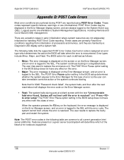
... booting. The user needs to replace the erroneous unit. These codes represent specific failures, warnings, or are exception cases in the BIOS setup determines whether the system pauses to the SEL with this type of error. The POST Error Pause option setting in the following table lists the supported POST Error Codes. Note: The POST error codes in the BIOS setup does not have any effect on this error. Major: The error message is displayed on the Error Manager...
... booting. The user needs to replace the erroneous unit. These codes represent specific failures, warnings, or are exception cases in the BIOS setup determines whether the system pauses to the SEL with this type of error. The POST Error Pause option setting in the following table lists the supported POST Error Codes. Note: The POST error codes in the BIOS setup does not have any effect on this error. Major: The error message is displayed on the Error Manager...

Service Guide
Page 8
... Intel® RMM4 NIC 41 Installing and Removing the Intel® RAID Smart Battery 41 Installing the Intel® RAID Smart Battery 41 Removing the Intel® RAID Smart Battery 42 Removing and Installing the Fixed Power Supply 43 Removing the Fixed Power Supply 43 Installing the Fixed Power Supply 44 Installing an Additional Hot-swap Power Supply Module 45 Replacing a Hot Swap Power Supply Module 45 Replacing the Power Distribution Board 46 Installing and Removing the Server Board 51 Removing the Server Board 51 Installing the Server Board 52 Replacing a Fixed Fan...53 Removing...
... Intel® RMM4 NIC 41 Installing and Removing the Intel® RAID Smart Battery 41 Installing the Intel® RAID Smart Battery 41 Removing the Intel® RAID Smart Battery 42 Removing and Installing the Fixed Power Supply 43 Removing the Fixed Power Supply 43 Installing the Fixed Power Supply 44 Installing an Additional Hot-swap Power Supply Module 45 Replacing a Hot Swap Power Supply Module 45 Replacing the Power Distribution Board 46 Installing and Removing the Server Board 51 Removing the Server Board 51 Installing the Server Board 52 Replacing a Fixed Fan...53 Removing...

Service Guide
Page 26
...(amber) if there is , CMOS Clear) ME Force Update BMC Force Update Password Clear Pins 1-2 2-3 1-2 2-3 1-2 2-3 1-2 2-3 1-2 2-3 System Results Pins 1-2 should be connected for normal system operation. (Default) The main system BIOS does not boot with a recovery BIOS image present. Jumper Name BIOS Recovery BIOS Default (that is a DIMM fault. The DIMM fault LEDs turn on . Server System Features DIMM Fault LEDs on Intel® Server Board S2400SC. System Jumpers The figure below shows the locations of System Jumpers on the server board help identify failed and failing DIMM slots...
...(amber) if there is , CMOS Clear) ME Force Update BMC Force Update Password Clear Pins 1-2 2-3 1-2 2-3 1-2 2-3 1-2 2-3 1-2 2-3 System Results Pins 1-2 should be connected for normal system operation. (Default) The main system BIOS does not boot with a recovery BIOS image present. Jumper Name BIOS Recovery BIOS Default (that is a DIMM fault. The DIMM fault LEDs turn on . Server System Features DIMM Fault LEDs on Intel® Server Board S2400SC. System Jumpers The figure below shows the locations of System Jumpers on the server board help identify failed and failing DIMM slots...
Service Guide
Page 102
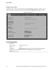
... no passwords set, Administrator is running in: Administrator or User. Back to [Main Screen] 86 Intel® Server Board S2400SC Intel® Server System P4000SC Family Service Guide Displays password level that appears when the BIOS Setup configuration utility is entered, unless an error has occurred. Logged in as : Option Values: Help Text: Comments: Information only. If an error has occurred, the Error Manager Screen appears instead. Main Screen Main Advanced Security Server Management Boot Options Boot Manager Logged...
... no passwords set, Administrator is running in: Administrator or User. Back to [Main Screen] 86 Intel® Server Board S2400SC Intel® Server System P4000SC Family Service Guide Displays password level that appears when the BIOS Setup configuration utility is entered, unless an error has occurred. Logged in as : Option Values: Help Text: Comments: Information only. If an error has occurred, the Error Manager Screen appears instead. Main Screen Main Advanced Security Server Management Boot Options Boot Manager Logged...

Service Guide
Page 130
... Mode Help Text: - This information is Disabled, the SATA Ports will be unavailable. 114 Intel® Server Board S2400SC Intel® Server System P4000SC Family Service Guide and any installed SATA devices will not operate. Various SATA/SAS Capable Controller configurations require the installation of these strings: Controller is a display showing the number of ports which provides Enhanced SATA functionality - AHCI enables the Advanced Host Controller Interface, which are available through the SCU controller, and whether they are configured for SATA or SAS. Server Utilities...
... Mode Help Text: - This information is Disabled, the SATA Ports will be unavailable. 114 Intel® Server Board S2400SC Intel® Server System P4000SC Family Service Guide and any installed SATA devices will not operate. Various SATA/SAS Capable Controller configurations require the installation of these strings: Controller is a display showing the number of ports which provides Enhanced SATA functionality - AHCI enables the Advanced Host Controller Interface, which are available through the SCU controller, and whether they are configured for SATA or SAS. Server Utilities...

Service Guide
Page 151
... reset and NMI Diagnostic Interrupt buttons on all boards. Comments: This option does not appear on the system's front panel. Comments: When Power On Password security is removed, that will also disable this option will ask for the Administrator password (see above). Back to [Security Screen] Intel® Server Board S2400SC Intel® Server System P4000SC Family Service Guide 135 The User Password only allows limited access to complete POST and boot the system. Server Utilities...
... reset and NMI Diagnostic Interrupt buttons on all boards. Comments: This option does not appear on the system's front panel. Comments: When Power On Password security is removed, that will also disable this option will ask for the Administrator password (see above). Back to [Security Screen] Intel® Server Board S2400SC Intel® Server System P4000SC Family Service Guide 135 The User Password only allows limited access to complete POST and boot the system. Server Utilities...


