Product Guide
Page 5
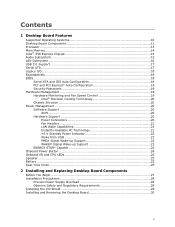
...19 Hardware Management 19 Hardware Monitoring and Fan Speed Control 19 Intel® Precision Cooling Technology 20 Chassis Intrusion 20 Power Management 20 Software Support 20 ACPI 20 Hardware Support 20 Power Connectors 20 Fan Headers 21 LAN Wake Capabilities 21 Instantly Available ... 23 Onboard Power Button 24 Onboard VR and CPU LEDs 25 Speaker...25 Battery ...25 Real-Time Clock 25 2 Installing and Replacing Desktop Board Components Before You Begin 27 Installation Precautions 28 Prevent Power Supply Overload 28 Observe Safety and Regulatory Requirements 28 Installing the...
...19 Hardware Management 19 Hardware Monitoring and Fan Speed Control 19 Intel® Precision Cooling Technology 20 Chassis Intrusion 20 Power Management 20 Software Support 20 ACPI 20 Hardware Support 20 Power Connectors 20 Fan Headers 21 LAN Wake Capabilities 21 Instantly Available ... 23 Onboard Power Button 24 Onboard VR and CPU LEDs 25 Speaker...25 Battery ...25 Real-Time Clock 25 2 Installing and Replacing Desktop Board Components Before You Begin 27 Installation Precautions 28 Prevent Power Supply Overload 28 Observe Safety and Regulatory Requirements 28 Installing the...
Product Guide
Page 20
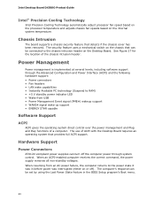
...enabled computer receives the correct command, the power supply removes all non-standby voltages. When resuming from an AC power failure, the computer returns to RAM) • +5 V standby power indicator LED • Wake from USB • Power Management Event signal (PME#) wakeup support &#... over the power management and Plug and Play functions of a computer. See Figure 27 for the location of ACPI with the Desktop Board requires an operating system that provides full ACPI support. Intel Desktop Board DX58SO Product Guide Intel® Precision Cooling Technology Intel Precision Cooling ...
...enabled computer receives the correct command, the power supply removes all non-standby voltages. When resuming from an AC power failure, the computer returns to RAM) • +5 V standby power indicator LED • Wake from USB • Power Management Event signal (PME#) wakeup support &#... over the power management and Plug and Play functions of a computer. See Figure 27 for the location of ACPI with the Desktop Board requires an operating system that provides full ACPI support. Intel Desktop Board DX58SO Product Guide Intel® Precision Cooling Technology Intel Precision Cooling ...
Product Guide
Page 27
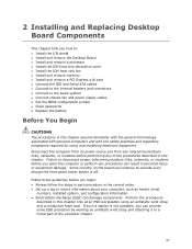
...I/O shield • Install and remove the Desktop Board • Install and remove a processor •... Connect to the audio system • Connect chassis fan and power supply cables • Set the BIOS configuration jumper • Clear ...power, telecommunications links, networks, or modems before performing any telecommunications links, networks, or modems before you begin: • Always follow the steps in each procedure in this chapter assume familiarity with the general terminology associated with personal computers and with the safety practices and regulatory compliance required...
...I/O shield • Install and remove the Desktop Board • Install and remove a processor •... Connect to the audio system • Connect chassis fan and power supply cables • Set the BIOS configuration jumper • Clear ...power, telecommunications links, networks, or modems before performing any telecommunications links, networks, or modems before you begin: • Always follow the steps in each procedure in this chapter assume familiarity with the general terminology associated with personal computers and with the safety practices and regulatory compliance required...

Product Guide
Page 28
... power supply, make sure that instruct you increase your computer meets safety and regulatory requirements. If you install and test the Intel Desktop Board, observe all the modules within the computer is less than the output current rating of each of all warnings and cautions in this section and the instructions supplied with regional laws and regulations. Intel Desktop Board DX58SO...
... power supply, make sure that instruct you increase your computer meets safety and regulatory requirements. If you install and test the Intel Desktop Board, observe all the modules within the computer is less than the output current rating of each of all warnings and cautions in this section and the instructions supplied with regional laws and regulations. Intel Desktop Board DX58SO...

Product Guide
Page 37
...that provided by the IOH passive heat sink, you can connect to the board's 3-pin IOH fan header to the IOH fan header (Figure 17, D). Slide the four legs of the fan. Attach the fan power connector to power the fan. Figure 17. You can add a fan to the fan ...push down as indicated by using the four screws (Figure 17, A) and nuts Figure 17, C) supplied with the fan. Installing and Replacing Desktop Board Components Installing the IOH Cooling Fan (Optional) If your system application requires more cooling than that the fan airflow is down until the bracket "clicks" into place. 3. ...
...that provided by the IOH passive heat sink, you can connect to the board's 3-pin IOH fan header to the IOH fan header (Figure 17, D). Slide the four legs of the fan. Attach the fan power connector to power the fan. Figure 17. You can add a fan to the fan ...push down as indicated by using the four screws (Figure 17, A) and nuts Figure 17, C) supplied with the fan. Installing and Replacing Desktop Board Components Installing the IOH Cooling Fan (Optional) If your system application requires more cooling than that the fan airflow is down until the bracket "clicks" into place. 3. ...

Product Guide
Page 54
Figure 30. The 2 x 12 pin main power connector (Figure 30, D) is required with 2 x 10 connectors. Use of the power connectors. CAUTION Failure to use an appropriate power supply and/or not connecting the 12 V (Figure 30, A) power connector to the Desktop Board may not function properly. Connecting Power Supply Cables 54 Intel Desktop Board DX58SO Product Guide Connecting Power Supply Cables Figure 30 shows the location of...
Figure 30. The 2 x 12 pin main power connector (Figure 30, D) is required with 2 x 10 connectors. Use of the power connectors. CAUTION Failure to use an appropriate power supply and/or not connecting the 12 V (Figure 30, A) power connector to the Desktop Board may not function properly. Connecting Power Supply Cables 54 Intel Desktop Board DX58SO Product Guide Connecting Power Supply Cables Figure 30 shows the location of...

Product Guide
Page 55
... program. Connect the 12 V processor core voltage power supply cable to the 2 x 12 pin connector. 4. Figure 31. Installing and Replacing Desktop Board Components 1. If additional power is required, connect the appropriate power supply cable to either the 1 x 4 auxiliary PCI Express graphics power connector or to the SATAstyle auxiliary PCI Express graphics power connector or to be done in unreliable computer...
... program. Connect the 12 V processor core voltage power supply cable to the 2 x 12 pin connector. 4. Figure 31. Installing and Replacing Desktop Board Components 1. If additional power is required, connect the appropriate power supply cable to either the 1 x 4 auxiliary PCI Express graphics power connector or to the SATAstyle auxiliary PCI Express graphics power connector or to be done in unreliable computer...

Product Guide
Page 83
... I/O cable shielding and filtering • Mounting, grounding, and bonding requirements • Keying connectors when mating the wrong connectors could be required on a representative sample of the newly completed computer. 83 Regulatory Compliance Korean Class B statement translation: This is household equipment that the power supply and other non-residential environments. Pay close attention to comply...
... I/O cable shielding and filtering • Mounting, grounding, and bonding requirements • Keying connectors when mating the wrong connectors could be required on a representative sample of the newly completed computer. 83 Regulatory Compliance Korean Class B statement translation: This is household equipment that the power supply and other non-residential environments. Pay close attention to comply...

Product Guide
Page 85
... Ensure that the chassis and certain components; Typical product certifications include: In Europe The CE marking signifies compliance with safety requirements. In Canada A nationally recognized certification mark such as applicable), should be UL listed or recognized and suitable for the... Low Voltage directive (as CSA or cUL signifies compliance with all applicable European requirements. In the United States A certification mark by a Nationally Recognized Testing Laboratory (NRTL) such as the power supply, peripheral drives, wiring, and cables; If the chassis and other directives,...
... Ensure that the chassis and certain components; Typical product certifications include: In Europe The CE marking signifies compliance with safety requirements. In Canada A nationally recognized certification mark such as applicable), should be UL listed or recognized and suitable for the... Low Voltage directive (as CSA or cUL signifies compliance with all applicable European requirements. In the United States A certification mark by a Nationally Recognized Testing Laboratory (NRTL) such as the power supply, peripheral drives, wiring, and cables; If the chassis and other directives,...


