Product Guide
Page 6
Intel Desktop Board DP55SB Product Guide Installing the I/O Shield 33 Installing and Removing the Desktop Board 34 Installing and Removing a Processor 35 Installing a Processor 35 Installing the Processor Fan Heat Sink 40 Connecting the Processor Fan Heat Sink Cable 40 Removing ...the Bluetooth Antenna 58 Setting the BIOS Configuration Jumper 59 Clearing Passwords 60 Replacing the Battery 61 3 Updating the BIOS Updating the BIOS with the Intel® Express BIOS Update Utility 67 Updating the BIOS with the ISO Image BIOS Update File or the Iflash Memory Update Utility 68 Obtaining the...
Intel Desktop Board DP55SB Product Guide Installing the I/O Shield 33 Installing and Removing the Desktop Board 34 Installing and Removing a Processor 35 Installing a Processor 35 Installing the Processor Fan Heat Sink 40 Connecting the Processor Fan Heat Sink Cable 40 Removing ...the Bluetooth Antenna 58 Setting the BIOS Configuration Jumper 59 Clearing Passwords 60 Replacing the Battery 61 3 Updating the BIOS Updating the BIOS with the Intel® Express BIOS Update Utility 67 Updating the BIOS with the ISO Image BIOS Update File or the Iflash Memory Update Utility 68 Obtaining the...
Product Guide
Page 7
Installing the I/O Shield 33 9. Unlatch the Socket Lever 35 11. Use DDR3 DIMMs 43 22. Installing a PCI Express x16 Graphics Card 46 24. Contents A Error Messages and Indicators ... Memory Configuration with Three DIMMs 42 21. Removing a PCI Express x16 Graphics Card 47 25. Remove the Socket Cover 37 13. Internal Headers 50 vii Intel Desktop Board DP55SB Components 12 2. Installing a DIMM 44 23. Connecting the Serial ATA Cables 49 27. Location of the Back to the Processor Fan Header 40 18. Secure...
Installing the I/O Shield 33 9. Unlatch the Socket Lever 35 11. Use DDR3 DIMMs 43 22. Installing a PCI Express x16 Graphics Card 46 24. Contents A Error Messages and Indicators ... Memory Configuration with Three DIMMs 42 21. Removing a PCI Express x16 Graphics Card 47 25. Remove the Socket Cover 37 13. Internal Headers 50 vii Intel Desktop Board DP55SB Components 12 2. Installing a DIMM 44 23. Connecting the Serial ATA Cables 49 27. Location of the Back to the Processor Fan Header 40 18. Secure...
Product Guide
Page 31
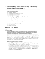
... safety practices and regulatory compliance required for using an antistatic wrist strap and a conductive foam pad. 2 Installing and Replacing Desktop Board Components This chapter tells you open the computer or perform any of the computer chassis. 31 Disconnect the computer from its ...power source and from any telecommunications links, networks, or modems before you how to: • Install the I/O shield • Install and remove the Desktop Board • Install and remove a processor • Install and remove memory • Install and remove a PCI Express x16 graphics...
... safety practices and regulatory compliance required for using an antistatic wrist strap and a conductive foam pad. 2 Installing and Replacing Desktop Board Components This chapter tells you open the computer or perform any of the computer chassis. 31 Disconnect the computer from its ...power source and from any telecommunications links, networks, or modems before you how to: • Install the I/O shield • Install and remove the Desktop Board • Install and remove a processor • Install and remove memory • Install and remove a PCI Express x16 graphics...

Product Guide
Page 33
... transmissions, protects internal components from the chassis supplier. Installing and Replacing Desktop Board Components Installing the I/O Shield The Desktop Board comes with an I /O Shield 33 Figure 8. If the shield does not fit, obtain a properly sized shield from dust and foreign objects, and promotes correct airflow within the chassis. Installing the I /O shield. Install the I/O shield before installing the Desktop Board in the chassis.
... transmissions, protects internal components from the chassis supplier. Installing and Replacing Desktop Board Components Installing the I/O Shield The Desktop Board comes with an I /O Shield 33 Figure 8. If the shield does not fit, obtain a properly sized shield from dust and foreign objects, and promotes correct airflow within the chassis. Installing the I /O shield. Install the I/O shield before installing the Desktop Board in the chassis.

Product Guide
Page 53
...FCC Class B requirements, even if no pin) Pin Signal Name 2 TPA1- 4 Ground 6 TPA2- 8 +12 V 10 Ground 53 Installing and Replacing Desktop Board Components USB 2.0 Headers Figure 27, F shows the location of the IEEE 1394a header. Table 9. Table 10 shows the pin assignments and signal names for... each USB 2.0 header. Use a shielded cable that have an unshielded cable attached to the cable. IEEE 1394a Header Figure 27, G shows the location of the USB 2.0 headers. Table...
...FCC Class B requirements, even if no pin) Pin Signal Name 2 TPA1- 4 Ground 6 TPA2- 8 +12 V 10 Ground 53 Installing and Replacing Desktop Board Components USB 2.0 Headers Figure 27, F shows the location of the IEEE 1394a header. Table 9. Table 10 shows the pin assignments and signal names for... each USB 2.0 header. Use a shielded cable that have an unshielded cable attached to the cable. IEEE 1394a Header Figure 27, G shows the location of the USB 2.0 headers. Table...

Product Guide
Page 89
... Class B EMC testing and are not Class B EMC compliant before integration, then EMC testing may be required on a representative sample of certifications • External I/O cable shielding and filtering • Mounting, grounding, and bonding requirements • Keying connectors when mating the wrong connectors could be hazardous If the power supply and other...
... Class B EMC testing and are not Class B EMC compliant before integration, then EMC testing may be required on a representative sample of certifications • External I/O cable shielding and filtering • Mounting, grounding, and bonding requirements • Keying connectors when mating the wrong connectors could be hazardous If the power supply and other...