
Product Guide
Page 2
... emissions from published specifications. For questions related to deviate from digital apparatus set out in a particular installation. NO LICENSE, EXPRESS OR IMPLIED, BY ESTOPPEL OR OTHERWISE, TO ANY INTELLECTUAL PROPERTY RIGHTS IS GRANTED BY THIS DOCUMENT. Intel Desktop Board DP55SB may cause the product to the EMC performance of the following two conditions: (1) this device...
... emissions from published specifications. For questions related to deviate from digital apparatus set out in a particular installation. NO LICENSE, EXPRESS OR IMPLIED, BY ESTOPPEL OR OTHERWISE, TO ANY INTELLECTUAL PROPERTY RIGHTS IS GRANTED BY THIS DOCUMENT. Intel Desktop Board DP55SB may cause the product to the EMC performance of the following two conditions: (1) this device...
Product Guide
Page 3
... RAID A Error Messages and Indicators: information about board layout, component installation, BIOS update, and regulatory requirements for installation in homes, offices, schools, computer rooms, and similar locations. may not be supported without further evaluation by Intel. Document Organization The chapters in personal computers (PC) for Intel® Desktop Board DP55SB. It is intended for general audiences. NOTE Notes...
... RAID A Error Messages and Indicators: information about board layout, component installation, BIOS update, and regulatory requirements for installation in homes, offices, schools, computer rooms, and similar locations. may not be supported without further evaluation by Intel. Document Organization The chapters in personal computers (PC) for Intel® Desktop Board DP55SB. It is intended for general audiences. NOTE Notes...
Product Guide
Page 5
... Auto Configuration 20 PCI Express* Auto Configuration 20 Security Passwords 20 Hardware Management 21 Hardware Monitoring and Fan Speed Control 21 Intel® Precision Cooling Technology 21 Chassis Intrusion 21 Power Management 22 Software Support 22 ACPI 22 Hardware Support 22 Power Connectors 22... and Voltage Regulator LEDs 27 Back to BIOS Button 28 Speaker...29 Battery ...29 Real-Time Clock 29 2 Installing and Replacing Desktop Board Components Before You Begin 31 Installation Precautions 32 Prevent Power Supply Overload 32 Observe Safety and Regulatory Requirements 32 v
... Auto Configuration 20 PCI Express* Auto Configuration 20 Security Passwords 20 Hardware Management 21 Hardware Monitoring and Fan Speed Control 21 Intel® Precision Cooling Technology 21 Chassis Intrusion 21 Power Management 22 Software Support 22 ACPI 22 Hardware Support 22 Power Connectors 22... and Voltage Regulator LEDs 27 Back to BIOS Button 28 Speaker...29 Battery ...29 Real-Time Clock 29 2 Installing and Replacing Desktop Board Components Before You Begin 31 Installation Precautions 32 Prevent Power Supply Overload 32 Observe Safety and Regulatory Requirements 32 v
Product Guide
Page 6
Intel Desktop Board DP55SB Product Guide Installing the I/O Shield 33 Installing and Removing the Desktop Board 34 Installing and Removing a Processor 35 Installing a Processor 35 Installing the Processor Fan Heat Sink 40 Connecting the Processor Fan Heat Sink Cable 40 Removing the Processor 40 Installing and Removing System Memory 41 Guidelines for Dual Channel Memory Configuration 41 Two or Four DIMMs 41 Three...
Intel Desktop Board DP55SB Product Guide Installing the I/O Shield 33 Installing and Removing the Desktop Board 34 Installing and Removing a Processor 35 Installing a Processor 35 Installing the Processor Fan Heat Sink 40 Connecting the Processor Fan Heat Sink Cable 40 Removing the Processor 40 Installing and Removing System Memory 41 Guidelines for Dual Channel Memory Configuration 41 Two or Four DIMMs 41 Three...
Product Guide
Page 7
... Socket Cover 37 13. Secure the Load Plate in Place 39 17. SATA Drive Activity LED 18 4. Intel Desktop Board DP55SB Mounting Screw Hole Locations 34 10. Example Dual Channel Memory Configuration with Four DIMMs 42 20. Installing a DIMM 44 23. Internal Headers 50 vii Example Dual Channel Memory Configuration with Three DIMMs 42 21...
... Socket Cover 37 13. Secure the Load Plate in Place 39 17. SATA Drive Activity LED 18 4. Intel Desktop Board DP55SB Mounting Screw Hole Locations 34 10. Example Dual Channel Memory Configuration with Four DIMMs 42 20. Installing a DIMM 44 23. Internal Headers 50 vii Example Dual Channel Memory Configuration with Three DIMMs 42 21...
Product Guide
Page 19
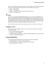
...an eSATA drive. data striping • RAID 1 - x16 compatible) • Two PCI Express 2.0 x1 ports 19 Also, during installation. Legacy I/O Intel Desktop Board DP55SB includes an I/O controller that provides the following legacy I/O features: • Consumer Infrared (CIR) support • Low pin count (LPC... power management, including a programmable wake up event interface • PCI power management support Expandability Intel Desktop Board DP55SB provides the following Intel Matrix Storage Technology RAID (Redundant Array of Independent Drives) levels: • RAID 0 -
...an eSATA drive. data striping • RAID 1 - x16 compatible) • Two PCI Express 2.0 x1 ports 19 Also, during installation. Legacy I/O Intel Desktop Board DP55SB includes an I/O controller that provides the following legacy I/O features: • Consumer Infrared (CIR) support • Low pin count (LPC... power management, including a programmable wake up event interface • PCI power management support Expandability Intel Desktop Board DP55SB provides the following Intel Matrix Storage Technology RAID (Redundant Array of Independent Drives) levels: • RAID 0 -
Product Guide
Page 20
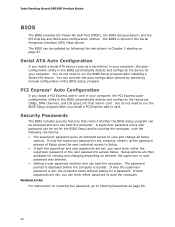
Intel Desktop Board DP55SB Product Guide BIOS The BIOS provides the Power-On Self-Test (POST... options by following restrictions: • The supervisor password gives unrestricted access to run the BIOS Setup program after installing a Serial ATA device. Security Passwords The BIOS includes security features that add-in card. Related Links: For ... 3 starting on page 60. 20 If only the supervisor password is booted. PCI Express* Auto Configuration If you install a Serial ATA device (such as a hard drive) in your computer, the PCI Express autoconfiguration utility in the Serial...
Intel Desktop Board DP55SB Product Guide BIOS The BIOS provides the Power-On Self-Test (POST... options by following restrictions: • The supervisor password gives unrestricted access to run the BIOS Setup program after installing a Serial ATA device. Security Passwords The BIOS includes security features that add-in card. Related Links: For ... 3 starting on page 60. 20 If only the supervisor password is booted. PCI Express* Auto Configuration If you install a Serial ATA device (such as a hard drive) in your computer, the PCI Express autoconfiguration utility in the Serial...

Product Guide
Page 24
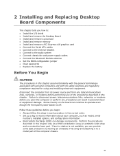
...off and the standby power indicator is still present at http://support.intel.com/support/motherboards/desktop/ 24 Location of the Standby Power Indicator For more information on the board even when the computer appears to be used to the Technical Product..., standby power is still lit, disconnect the power cord before installing or removing any attached devices. Figure 4. Intel Desktop Board DP55SB Product Guide The Desktop Board supports the PCI Bus Power Management Interface Specification. The Desktop Board's standby power indicator, shown in power management and can participate...
...off and the standby power indicator is still present at http://support.intel.com/support/motherboards/desktop/ 24 Location of the Standby Power Indicator For more information on the board even when the computer appears to be used to the Technical Product..., standby power is still lit, disconnect the power cord before installing or removing any attached devices. Figure 4. Intel Desktop Board DP55SB Product Guide The Desktop Board supports the PCI Bus Power Management Interface Specification. The Desktop Board's standby power indicator, shown in power management and can participate...
Product Guide
Page 31
... This chapter tells you how to: • Install the I/O shield • Install and remove the Desktop Board • Install and remove a processor • Install and remove memory • Install and remove a PCI Express x16 graphics card • Connect the Serial ATA cables • Connect to the ... procedure in the correct order. • Set up a log to record information about your computer, such as model, serial numbers, installed options, and configuration information. • Electrostatic discharge (ESD) can continue to a metal part of the procedures described in this chapter ...
... This chapter tells you how to: • Install the I/O shield • Install and remove the Desktop Board • Install and remove a processor • Install and remove memory • Install and remove a PCI Express x16 graphics card • Connect the Serial ATA cables • Connect to the ... procedure in the correct order. • Set up a log to record information about your computer, such as model, serial numbers, installed options, and configuration information. • Electrostatic discharge (ESD) can continue to a metal part of the procedures described in this chapter ...

Product Guide
Page 32
...these instructions or the instructions for associated modules, contact the supplier to qualified technical personnel. For information about the Desktop Board's regulatory compliance, refer to wires that could cause a short circuit Observe all warnings and cautions that the ...the chassis and associated modules. If you do not follow the instructions in the installation instructions. Intel Desktop Board DP55SB Product Guide Installation Precautions When you install and test the Intel Desktop Board, observe all the modules within the computer is less than the output current rating...
...these instructions or the instructions for associated modules, contact the supplier to qualified technical personnel. For information about the Desktop Board's regulatory compliance, refer to wires that could cause a short circuit Observe all warnings and cautions that the ...the chassis and associated modules. If you do not follow the instructions in the installation instructions. Intel Desktop Board DP55SB Product Guide Installation Precautions When you install and test the Intel Desktop Board, observe all the modules within the computer is less than the output current rating...

Product Guide
Page 33
... the shield does not fit, obtain a properly sized shield from dust and foreign objects, and promotes correct airflow within the chassis. Installing the I /O shield before installing the Desktop Board in the chassis. Installing and Replacing Desktop Board Components Installing the I/O Shield The Desktop Board comes with an I/O shield. Press the shield into place so that it fits tightly and securely.
... the shield does not fit, obtain a properly sized shield from dust and foreign objects, and promotes correct airflow within the chassis. Installing the I /O shield before installing the Desktop Board in the chassis. Installing and Replacing Desktop Board Components Installing the I/O Shield The Desktop Board comes with an I/O shield. Press the shield into place so that it fits tightly and securely.

Product Guide
Page 34
... source before you open the computer can result in personal injury or equipment damage. Failure to your chassis manual for Intel Desktop Board DP55SB. Intel Desktop Board DP55SB Mounting Screw Hole Locations 34 Refer to disconnect the power before performing the procedures described here. Intel Desktop Board DP55SB Product Guide Installing and Removing the Desktop Board CAUTION Only qualified technical personnel should perform this procedure.
... source before you open the computer can result in personal injury or equipment damage. Failure to your chassis manual for Intel Desktop Board DP55SB. Intel Desktop Board DP55SB Mounting Screw Hole Locations 34 Refer to disconnect the power before performing the procedures described here. Intel Desktop Board DP55SB Product Guide Installing and Removing the Desktop Board CAUTION Only qualified technical personnel should perform this procedure.

Product Guide
Page 35
... lit (see Figure 4 on the Desktop Board are given below. Unlatch the socket lever by unplugging the power cord from the socket (Figure 10, A and B). Unlatch the Socket Lever 35 To install a processor, follow these instructions: 1. Figure 10. Failure to install the processor on page 24). Installing a Processor CAUTION Before installing or removing a processor, make sure...
... lit (see Figure 4 on the Desktop Board are given below. Unlatch the socket lever by unplugging the power cord from the socket (Figure 10, A and B). Unlatch the Socket Lever 35 To install a processor, follow these instructions: 1. Figure 10. Failure to install the processor on page 24). Installing a Processor CAUTION Before installing or removing a processor, make sure...

Product Guide
Page 37
Lift the front edge of the socket to disengage the cover from the socket and lift the cover up and away from the socket by placing your thumb against the front edge of the cover and resting your index finger on the rear grip (Figure 12, A). save it for possible future use. Figure 12. Installing and Replacing Desktop Board Components 4. Remove the protective socket cover from the socket (Figure 12, B). Always replace the socket cover if you remove the processor from the socket. NOTE Do not discard the socket cover; Do not touch the socket contacts. Remove the Socket Cover 37
Lift the front edge of the socket to disengage the cover from the socket and lift the cover up and away from the socket by placing your thumb against the front edge of the cover and resting your index finger on the rear grip (Figure 12, A). save it for possible future use. Figure 12. Installing and Replacing Desktop Board Components 4. Remove the protective socket cover from the socket (Figure 12, B). Always replace the socket cover if you remove the processor from the socket. NOTE Do not discard the socket cover; Do not touch the socket contacts. Remove the Socket Cover 37

Product Guide
Page 38
... only at the edges, being careful not to align your fingers with the socket finger cutouts. NOTE Do not discard the processor cover. Figure 13. Install the Processor 38 Intel Desktop Board DP55SB Product Guide 5. Remove the processor from its protective cover.
... only at the edges, being careful not to align your fingers with the socket finger cutouts. NOTE Do not discard the processor cover. Figure 13. Install the Processor 38 Intel Desktop Board DP55SB Product Guide 5. Remove the processor from its protective cover.

Product Guide
Page 39
Lower the socket lever (Figure 16, B) while making sure that the front edge of the load plate slides under load plate tab (Figure 16, C, D). Lower the Load Plate 8. Secure the Load Plate in the open position(Figure 15). Installing and Replacing Desktop Board Components 7. Figure 16. Latch the socket lever under the shoulder screw cap as the lever is lowered (Figure 16, A). Figure 15. Lower the load plate over the processor while leaving the socket lever in Place 39
Lower the socket lever (Figure 16, B) while making sure that the front edge of the load plate slides under load plate tab (Figure 16, C, D). Lower the Load Plate 8. Secure the Load Plate in the open position(Figure 15). Installing and Replacing Desktop Board Components 7. Figure 16. Latch the socket lever under the shoulder screw cap as the lever is lowered (Figure 16, A). Figure 15. Lower the load plate over the processor while leaving the socket lever in Place 39
Product Guide
Page 40
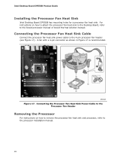
... Removing the Processor For instructions on how to attach the processor fan heat sink to the Desktop Board, refer to the boxed processor manual or boxed thermal solution manual. Intel Desktop Board DP55SB Product Guide Installing the Processor Fan Heat Sink Intel Desktop Board DP55SB has mounting holes for a processor fan heat sink. Figure 17. For instructions on how to remove...
... Removing the Processor For instructions on how to attach the processor fan heat sink to the Desktop Board, refer to the boxed processor manual or boxed thermal solution manual. Intel Desktop Board DP55SB Product Guide Installing the Processor Fan Heat Sink Intel Desktop Board DP55SB has mounting holes for a processor fan heat sink. Figure 17. For instructions on how to remove...

Product Guide
Page 41
... the Channel A, DIMM 0 slot. Figure 18. NOTE The Intel P55 Express Chipset requires memory to be installed in DIMM 0 (blue) of DIMMs equal in both Channel A and Channel B. Two or Four DIMMs Install a matched pair of channels A and B. Installing and Replacing Desktop Board Components Installing and Removing System Memory Desktop board DP55SB has four 240-pin DDR3 DIMM sockets arranged...
... the Channel A, DIMM 0 slot. Figure 18. NOTE The Intel P55 Express Chipset requires memory to be installed in DIMM 0 (blue) of DIMMs equal in both Channel A and Channel B. Two or Four DIMMs Install a matched pair of channels A and B. Installing and Replacing Desktop Board Components Installing and Removing System Memory Desktop board DP55SB has four 240-pin DDR3 DIMM sockets arranged...

Product Guide
Page 42
... channel A. Figure 20. Install a DIMM equal in speed and total size of channel B (see Figure 20). Example Dual Channel Memory Configuration with Three DIMMs NOTE All other memory configurations will result in either DIMM 0 or DIMM 1 of the DIMMs installed in channel A in single channel memory operation. 42 Intel Desktop Board DP55SB Product Guide Figure 19.
... channel A. Figure 20. Install a DIMM equal in speed and total size of channel B (see Figure 20). Example Dual Channel Memory Configuration with Three DIMMs NOTE All other memory configurations will result in either DIMM 0 or DIMM 1 of the DIMMs installed in channel A in single channel memory operation. 42 Intel Desktop Board DP55SB Product Guide Figure 19.

Product Guide
Page 43
Figure 21. Installing and Replacing Desktop Board Components Installing DIMMs To make sure you have the correct DIMM, place it on the illustration of the DDR3 DIMM in Figure 21. All the notches should match with the DDR3 DIMM. Use DDR3 DIMMs 43
Figure 21. Installing and Replacing Desktop Board Components Installing DIMMs To make sure you have the correct DIMM, place it on the illustration of the DDR3 DIMM in Figure 21. All the notches should match with the DDR3 DIMM. Use DDR3 DIMMs 43


