Product Guide
Page 6
Intel Desktop Board DP55SB Product Guide Installing the I/O Shield 33 Installing and Removing the Desktop Board 34 Installing and Removing a Processor 35 Installing a Processor 35 Installing the Processor Fan Heat Sink 40 Connecting the Processor Fan Heat Sink Cable ...56 Connecting Chassis Fan Cables 56 Connecting Power Supply Cables 57 Connecting the Bluetooth Antenna 58 Setting the BIOS Configuration Jumper 59 Clearing Passwords 60 Replacing the Battery 61 3 Updating the BIOS Updating the BIOS with the Intel® Express BIOS Update Utility 67 Updating the BIOS with the ISO Image...
Intel Desktop Board DP55SB Product Guide Installing the I/O Shield 33 Installing and Removing the Desktop Board 34 Installing and Removing a Processor 35 Installing a Processor 35 Installing the Processor Fan Heat Sink 40 Connecting the Processor Fan Heat Sink Cable ...56 Connecting Chassis Fan Cables 56 Connecting Power Supply Cables 57 Connecting the Bluetooth Antenna 58 Setting the BIOS Configuration Jumper 59 Clearing Passwords 60 Replacing the Battery 61 3 Updating the BIOS Updating the BIOS with the Intel® Express BIOS Update Utility 67 Updating the BIOS with the ISO Image...
Product Guide
Page 8
...Use Period Mark 86 21. Product Certification Markings 90 viii Connecting Power Supply Cables 57 31. Connecting the Bluetooth Antenna 58 32. Intel Desktop Board DP55SB China RoHS Material Self Declaration Table 87 Tables 1. Chassis Intrusion Header Signal Names 54 12. Front-panel ...Marks 85 20. Front Panel Header Signal Names 52 8. Intel Desktop Board DP55SB Product Guide 28. Location of the Chassis Fan Headers 56 30. Front Panel CIR Receiver (Input) Header Signal Names 51 6. Intel Desktop Board DP55SB Components 13 3. IEEE 1394a Header Signal Names 53 11....
...Use Period Mark 86 21. Product Certification Markings 90 viii Connecting Power Supply Cables 57 31. Connecting the Bluetooth Antenna 58 32. Intel Desktop Board DP55SB China RoHS Material Self Declaration Table 87 Tables 1. Chassis Intrusion Header Signal Names 54 12. Front-panel ...Marks 85 20. Front Panel Header Signal Names 52 8. Intel Desktop Board DP55SB Product Guide 28. Location of the Chassis Fan Headers 56 30. Front Panel CIR Receiver (Input) Header Signal Names 51 6. Intel Desktop Board DP55SB Components 13 3. IEEE 1394a Header Signal Names 53 11....

Product Guide
Page 17
... Mb/s data rate 100 Mb/s data rate 1000 Mb/s data rate Bluetooth* Technology Support The Desktop Board includes a Bluetooth* module (Figure 1, GG). Desktop Board Features Two LEDs are built into the RJ-45 LAN connector located on how to connect the antenna provided with the board to connect with a variety of the LAN as Microsoft Windows Vista and...
... Mb/s data rate 100 Mb/s data rate 1000 Mb/s data rate Bluetooth* Technology Support The Desktop Board includes a Bluetooth* module (Figure 1, GG). Desktop Board Features Two LEDs are built into the RJ-45 LAN connector located on how to connect the antenna provided with the board to connect with a variety of the LAN as Microsoft Windows Vista and...
Product Guide
Page 31
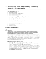
... the Desktop Board • Install and remove a processor • Install and remove memory • Install and remove a PCI Express x16 graphics card • Connect the Serial ATA cables • Connect to the internal headers • Connect to the audio system • Connect chassis fan and power supply cables • Connect the Bluetooth Module antenna...
... the Desktop Board • Install and remove a processor • Install and remove memory • Install and remove a PCI Express x16 graphics card • Connect the Serial ATA cables • Connect to the internal headers • Connect to the audio system • Connect chassis fan and power supply cables • Connect the Bluetooth Module antenna...

Product Guide
Page 58
... the main power supply cable to the onboard Bluetooth module. In order to the SATA-style PCI Express graphics auxiliary power connector (Figure 30, B). If additional power is provided with Bluetooth-enabled devices, you must connect the antenna to the 2 x 12 pin connector (Figure 30, C). 4. Intel Desktop Board DP55SB Product Guide 1. Observe the precautions in "Before You...
... the main power supply cable to the onboard Bluetooth module. In order to the SATA-style PCI Express graphics auxiliary power connector (Figure 30, B). If additional power is provided with Bluetooth-enabled devices, you must connect the antenna to the 2 x 12 pin connector (Figure 30, C). 4. Intel Desktop Board DP55SB Product Guide 1. Observe the precautions in "Before You...