Product Guide
Page 5
Contents 1 Desktop Board Features Supported Operating Systems 11 Desktop Board Components 12 Processor ...14 Main Memory...15 Intel® P55 Express Chipset 16 Audio Subsystem 16 LAN Subsystem 16 Bluetooth* Technology Support 17 USB 2.0 Support 18 Serial ATA Support 18 Legacy I/O ...19 Expandability...19 BIOS ...20 Serial ATA ... 27 Back to BIOS Button 28 Speaker...29 Battery ...29 Real-Time Clock 29 2 Installing and Replacing Desktop Board Components Before You Begin 31 Installation Precautions 32 Prevent Power Supply Overload 32 Observe Safety and Regulatory Requirements 32 v
Contents 1 Desktop Board Features Supported Operating Systems 11 Desktop Board Components 12 Processor ...14 Main Memory...15 Intel® P55 Express Chipset 16 Audio Subsystem 16 LAN Subsystem 16 Bluetooth* Technology Support 17 USB 2.0 Support 18 Serial ATA Support 18 Legacy I/O ...19 Expandability...19 BIOS ...20 Serial ATA ... 27 Back to BIOS Button 28 Speaker...29 Battery ...29 Real-Time Clock 29 2 Installing and Replacing Desktop Board Components Before You Begin 31 Installation Precautions 32 Prevent Power Supply Overload 32 Observe Safety and Regulatory Requirements 32 v
Product Guide
Page 6
Intel Desktop Board DP55SB Product Guide Installing the I/O Shield 33 Installing and Removing the Desktop Board 34 Installing and Removing a Processor 35 Installing a Processor 35 Installing the Processor Fan Heat Sink 40 Connecting the Processor Fan Heat Sink Cable 40 Removing... the Audio System 55 Connecting Chassis Fan and Power Supply Cables 56 Connecting Chassis Fan Cables 56 Connecting Power Supply Cables 57 Connecting the Bluetooth Antenna 58 Setting the BIOS Configuration Jumper 59 Clearing Passwords 60 Replacing the Battery 61 3 Updating the BIOS Updating the BIOS with the...
Intel Desktop Board DP55SB Product Guide Installing the I/O Shield 33 Installing and Removing the Desktop Board 34 Installing and Removing a Processor 35 Installing a Processor 35 Installing the Processor Fan Heat Sink 40 Connecting the Processor Fan Heat Sink Cable 40 Removing... the Audio System 55 Connecting Chassis Fan and Power Supply Cables 56 Connecting Chassis Fan Cables 56 Connecting Power Supply Cables 57 Connecting the Bluetooth Antenna 58 Setting the BIOS Configuration Jumper 59 Clearing Passwords 60 Replacing the Battery 61 3 Updating the BIOS Updating the BIOS with the...
Product Guide
Page 8
...1394a Header Signal Names 53 11. S/PDIF Header Signal Names 54 13. BIOS Beep Codes 73 15. EMC Regulations 88 22. Intel Desktop Board DP55SB Components 13 3. Front Panel Intel HD Audio Header Signal Names 51 5. Back Panel CIR Header Emitter (Output) Header Signal Names 52 7. USB 2.0 Header Signal ...31. LAN Connector LEDs 17 4. Jumper Settings for the BIOS Setup Program Modes 60 14. Safety Standards 79 19. Connecting the Bluetooth Antenna 58 32. Removing the Battery 66 34. Lead-Free Second Level Interconnect Marks 85 20. Location of the BIOS Configuration Jumper...
...1394a Header Signal Names 53 11. S/PDIF Header Signal Names 54 13. BIOS Beep Codes 73 15. EMC Regulations 88 22. Intel Desktop Board DP55SB Components 13 3. Front Panel Intel HD Audio Header Signal Names 51 5. Back Panel CIR Header Emitter (Output) Header Signal Names 52 7. USB 2.0 Header Signal ...31. LAN Connector LEDs 17 4. Jumper Settings for the BIOS Setup Program Modes 60 14. Safety Standards 79 19. Connecting the Bluetooth Antenna 58 32. Removing the Battery 66 34. Lead-Free Second Level Interconnect Marks 85 20. Location of the BIOS Configuration Jumper...
Product Guide
Page 10
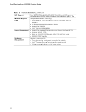
Intel Desktop Board DP55SB Product Guide Table 1. Feature Summary (continued) LAN Support Intel 82578DM Gigabit (10/100/1000 Mb/s) Ethernet LAN controller including an RJ-45 back panel connector with integrated status LEDs Wireless Support BIOS Integrated Bluetooth* technology • Intel® Platform Innovation Framework for extensible firmware interface • 16 Mb symmetrical flash memory device • Support...
Intel Desktop Board DP55SB Product Guide Table 1. Feature Summary (continued) LAN Support Intel 82578DM Gigabit (10/100/1000 Mb/s) Ethernet LAN controller including an RJ-45 back panel connector with integrated status LEDs Wireless Support BIOS Integrated Bluetooth* technology • Intel® Platform Innovation Framework for extensible firmware interface • 16 Mb symmetrical flash memory device • Support...

Product Guide
Page 13
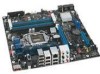
... front panel power LED header Front chassis fan header USB 2.0 headers IEEE 1394a header BIOS configuration jumper block Serial ATA connectors BlueTooth* module Chassis intrusion header Speaker 13 Desktop Board Features Table 2. Intel Desktop Board DP55SB Components Label A B C D E F G H I J K L M N O P Q R S T U V W X Y Z AA BB CC DD EE FF GG HH II Description Auxiliary PCI Express graphics power connector (SATA-style) PCI...
... front panel power LED header Front chassis fan header USB 2.0 headers IEEE 1394a header BIOS configuration jumper block Serial ATA connectors BlueTooth* module Chassis intrusion header Speaker 13 Desktop Board Features Table 2. Intel Desktop Board DP55SB Components Label A B C D E F G H I J K L M N O P Q R S T U V W X Y Z AA BB CC DD EE FF GG HH II Description Auxiliary PCI Express graphics power connector (SATA-style) PCI...

Product Guide
Page 17
These LEDs indicate the status of Bluetooth-enabled devices. LAN Connector LEDs LED A B LED Color Green N/A Green Yellow LED State Off On Blinking Off On On Indicates LAN link is not established...1000 Mb/s data rate Bluetooth* Technology Support The Desktop Board includes a Bluetooth* module (Figure 1, GG). Refer to Connecting the Bluetooth Antenna on page 58 for information on the back panel (see Figure 2). The Bluetooth module plus the included external antenna enables you to connect with the board to the Bluetooth module. 17 Figure 2. Desktop Board Features Two LEDs are built...
These LEDs indicate the status of Bluetooth-enabled devices. LAN Connector LEDs LED A B LED Color Green N/A Green Yellow LED State Off On Blinking Off On On Indicates LAN link is not established...1000 Mb/s data rate Bluetooth* Technology Support The Desktop Board includes a Bluetooth* module (Figure 1, GG). Refer to Connecting the Bluetooth Antenna on page 58 for information on the back panel (see Figure 2). The Bluetooth module plus the included external antenna enables you to connect with the board to the Bluetooth module. 17 Figure 2. Desktop Board Features Two LEDs are built...
Product Guide
Page 31
...Desktop Board • Install and remove a processor • Install and remove memory • Install and remove a PCI Express x16 graphics card • Connect the Serial ATA cables • Connect to the internal headers • Connect to the audio system • Connect chassis fan and power supply cables • Connect the Bluetooth...only at an ESD workstation using and modifying electronic equipment. If such a station is off. Some circuitry on the board can result in this chapter. Disconnect the computer from its power source and from any telecommunications links, networks, or ...
...Desktop Board • Install and remove a processor • Install and remove memory • Install and remove a PCI Express x16 graphics card • Connect the Serial ATA cables • Connect to the internal headers • Connect to the audio system • Connect chassis fan and power supply cables • Connect the Bluetooth...only at an ESD workstation using and modifying electronic equipment. If such a station is off. Some circuitry on the board can result in this chapter. Disconnect the computer from its power source and from any telecommunications links, networks, or ...

Product Guide
Page 58
... must connect the antenna to the mating connector on the end of the system chassis. In order to communicate with the desktop board. Attach the connector on the Bluetooth module (Figure 31, A). 3. Remove the paper backing from the antenna (Figure 31, C) and attach it to the... (Figure 30, B). Observe the precautions in "Before You Begin" on page 31. 2. Observe the precautions in "Before You Begin" on page 31. 2. Intel Desktop Board DP55SB Product Guide 1. Follow the steps below to connect the antenna to the 2 x 4 pin connector (Figure 30, A) . 3. Connect the 12 V processor ...
... must connect the antenna to the mating connector on the end of the system chassis. In order to communicate with the desktop board. Attach the connector on the Bluetooth module (Figure 31, A). 3. Remove the paper backing from the antenna (Figure 31, C) and attach it to the... (Figure 30, B). Observe the precautions in "Before You Begin" on page 31. 2. Observe the precautions in "Before You Begin" on page 31. 2. Intel Desktop Board DP55SB Product Guide 1. Follow the steps below to connect the antenna to the 2 x 4 pin connector (Figure 30, A) . 3. Connect the 12 V processor ...