Product Guide
Page 3
... Product Guide are used in this manual: CAUTION Cautions warn the user about board layout, component installation, BIOS update, and regulatory requirements for Intel® Desktop Board DP55SB. NOTE Notes call attention to important information. may not be supported without further evaluation by Intel. Preface This Product Guide gives information about how to prevent damage to hardware...
... Product Guide are used in this manual: CAUTION Cautions warn the user about board layout, component installation, BIOS update, and regulatory requirements for Intel® Desktop Board DP55SB. NOTE Notes call attention to important information. may not be supported without further evaluation by Intel. Preface This Product Guide gives information about how to prevent damage to hardware...
Product Guide
Page 5
...1 Desktop Board Features Supported Operating Systems 11 Desktop Board Components 12 Processor ...14 Main Memory...15 Intel® P55 Express Chipset 16 Audio Subsystem 16 LAN Subsystem 16 Bluetooth* Technology Support 17 USB 2.0 Support 18 Serial ATA Support 18 Legacy I/O ...19 Expandability...19 BIOS ...20... 25 Onboard Power Button 26 Processor and Voltage Regulator LEDs 27 Back to BIOS Button 28 Speaker...29 Battery ...29 Real-Time Clock 29 2 Installing and Replacing Desktop Board Components Before You Begin 31 Installation Precautions 32 Prevent Power Supply Overload 32 ...
...1 Desktop Board Features Supported Operating Systems 11 Desktop Board Components 12 Processor ...14 Main Memory...15 Intel® P55 Express Chipset 16 Audio Subsystem 16 LAN Subsystem 16 Bluetooth* Technology Support 17 USB 2.0 Support 18 Serial ATA Support 18 Legacy I/O ...19 Expandability...19 BIOS ...20... 25 Onboard Power Button 26 Processor and Voltage Regulator LEDs 27 Back to BIOS Button 28 Speaker...29 Battery ...29 Real-Time Clock 29 2 Installing and Replacing Desktop Board Components Before You Begin 31 Installation Precautions 32 Prevent Power Supply Overload 32 ...
Product Guide
Page 6
Intel Desktop Board DP55SB Product Guide Installing the I/O Shield 33 Installing and Removing the Desktop Board 34 Installing and Removing a Processor 35 Installing a Processor 35 Installing the Processor Fan Heat Sink 40 Connecting the Processor Fan Heat Sink...Supply Cables 57 Connecting the Bluetooth Antenna 58 Setting the BIOS Configuration Jumper 59 Clearing Passwords 60 Replacing the Battery 61 3 Updating the BIOS Updating the BIOS with the Intel® Express BIOS Update Utility 67 Updating the BIOS with the ISO Image BIOS Update File or the Iflash Memory Update Utility 68 ...
Intel Desktop Board DP55SB Product Guide Installing the I/O Shield 33 Installing and Removing the Desktop Board 34 Installing and Removing a Processor 35 Installing a Processor 35 Installing the Processor Fan Heat Sink 40 Connecting the Processor Fan Heat Sink...Supply Cables 57 Connecting the Bluetooth Antenna 58 Setting the BIOS Configuration Jumper 59 Clearing Passwords 60 Replacing the Battery 61 3 Updating the BIOS Updating the BIOS with the Intel® Express BIOS Update Utility 67 Updating the BIOS with the ISO Image BIOS Update File or the Iflash Memory Update Utility 68 ...
Product Guide
Page 7
...a PCI Express x16 Graphics Card 46 24. Removing a PCI Express x16 Graphics Card 47 25. Onboard Power Button 26 6. Intel Desktop Board DP55SB Mounting Screw Hole Locations 34 10. Connecting the Serial ATA Cables 49 27. Lift the Load Plate 36 12. Remove the Socket...) Compliance 89 Product Certifications 90 Board-Level Certification Markings 90 Chassis and Component Certifications 91 Figures 1. Connecting the Processor Fan Heat Sink Power Cable to BIOS Button 28 8. Contents A Error Messages and Indicators BIOS Error Codes 73 BIOS Error Messages 74 Port 80h POST...
...a PCI Express x16 Graphics Card 46 24. Removing a PCI Express x16 Graphics Card 47 25. Onboard Power Button 26 6. Intel Desktop Board DP55SB Mounting Screw Hole Locations 34 10. Connecting the Serial ATA Cables 49 27. Lift the Load Plate 36 12. Remove the Socket...) Compliance 89 Product Certifications 90 Board-Level Certification Markings 90 Chassis and Component Certifications 91 Figures 1. Connecting the Processor Fan Heat Sink Power Cable to BIOS Button 28 8. Contents A Error Messages and Indicators BIOS Error Codes 73 BIOS Error Messages 74 Port 80h POST...
Product Guide
Page 8
... 53 10. Safety Standards 79 19. Intel Desktop Board DP55SB Product Guide 28. Location of the BIOS Configuration Jumper Block 59 33. Location of the Chassis Fan Headers 56 30. Removing the Battery 66 34. POST Code LED Display 75 35. Intel Desktop Board DP55SB China RoHS Material Self Declaration Table 87 Tables 1. Intel Desktop Board DP55SB Components 13 3. Front Panel CIR Receiver...
... 53 10. Safety Standards 79 19. Intel Desktop Board DP55SB Product Guide 28. Location of the BIOS Configuration Jumper Block 59 33. Location of the Chassis Fan Headers 56 30. Removing the Battery 66 34. POST Code LED Display 75 35. Intel Desktop Board DP55SB China RoHS Material Self Declaration Table 87 Tables 1. Intel Desktop Board DP55SB Components 13 3. Front Panel CIR Receiver...
Product Guide
Page 10
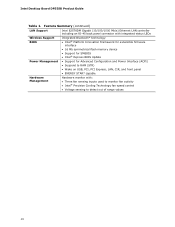
... Platform Innovation Framework for extensible firmware interface • 16 Mb symmetrical flash memory device • Support for SMBIOS • Intel® Express BIOS Update Power Management • Support for Advanced Configuration and Power Interface (ACPI) • Suspend to RAM (STR) •...* capable Hardware Management Hardware monitor with: • Three fan sensing inputs used to monitor fan activity • Intel® Precision Cooling Technology fan speed control • Voltage sensing to detect out of range values 10 Intel Desktop Board DP55SB Product Guide Table 1.
... Platform Innovation Framework for extensible firmware interface • 16 Mb symmetrical flash memory device • Support for SMBIOS • Intel® Express BIOS Update Power Management • Support for Advanced Configuration and Power Interface (ACPI) • Suspend to RAM (STR) •...* capable Hardware Management Hardware monitor with: • Three fan sensing inputs used to monitor fan activity • Intel® Precision Cooling Technology fan speed control • Voltage sensing to detect out of range values 10 Intel Desktop Board DP55SB Product Guide Table 1.

Product Guide
Page 13
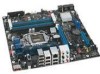
... CIR receiver (input) header Alternate front panel power LED header Front chassis fan header USB 2.0 headers IEEE 1394a header BIOS configuration jumper block Serial ATA connectors BlueTooth* module Chassis intrusion header Speaker 13 Intel Desktop Board DP55SB Components Label A B C D E F G H I J K L M N O P Q R S T U V W X Y Z AA BB CC DD EE FF GG HH II Description Auxiliary PCI Express graphics power connector...
... CIR receiver (input) header Alternate front panel power LED header Front chassis fan header USB 2.0 headers IEEE 1394a header BIOS configuration jumper block Serial ATA connectors BlueTooth* module Chassis intrusion header Speaker 13 Intel Desktop Board DP55SB Components Label A B C D E F G H I J K L M N O P Q R S T U V W X Y Z AA BB CC DD EE FF GG HH II Description Auxiliary PCI Express graphics power connector...

Product Guide
Page 14
.../desktop/chipsets/inde x.htm • BIOS and driver updates http://downloadcenter.intel.com/ • Integration information http://www.intel.com/support/go to http://processormatch.intel.com. 14 For information on Intel Desktop Board DP55SB consult the following online resources: • Intel Desktop Board DP55SB http://www.intel.com/products/motherboard/DP55SB/ index.htm • Desktop Board Support http://support.intel.com/support/motherboards/deskt op/DP55SB • Available configurations for Intel Desktop Board DP55SB...
.../desktop/chipsets/inde x.htm • BIOS and driver updates http://downloadcenter.intel.com/ • Integration information http://www.intel.com/support/go to http://processormatch.intel.com. 14 For information on Intel Desktop Board DP55SB consult the following online resources: • Intel Desktop Board DP55SB http://www.intel.com/products/motherboard/DP55SB/ index.htm • Desktop Board Support http://support.intel.com/support/motherboards/deskt op/DP55SB • Available configurations for Intel Desktop Board DP55SB...
Product Guide
Page 15
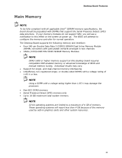
...with a voltage rating of 1.65 V or less NOTE Using a DIMM with a voltage rating higher than 4 GB because of BIOS and manual memory tuning. The Desktop Board supports the following memory and interface: • Four 240-pin Double Data Rate 3 (DDR3) SDRAM Dual Inline Memory Module (... report less than 1.65 V may vary. • Support for normal operation. Desktop Board Features Main Memory NOTE To be fully compliant with all applicable Intel ® SDRAM memory specifications, the board should be populated with gold-plated contacts arranged in graphics cards and other system resources...
...with a voltage rating of 1.65 V or less NOTE Using a DIMM with a voltage rating higher than 4 GB because of BIOS and manual memory tuning. The Desktop Board supports the following memory and interface: • Four 240-pin Double Data Rate 3 (DDR3) SDRAM Dual Inline Memory Module (... report less than 1.65 V may vary. • Support for normal operation. Desktop Board Features Main Memory NOTE To be fully compliant with all applicable Intel ® SDRAM memory specifications, the board should be populated with gold-plated contacts arranged in graphics cards and other system resources...

Product Guide
Page 18
... at USB 1.1 speeds. Disabling Hi-Speed USB in Figure 3. SATA Drive Activity LED 18 The Desktop Board includes a SATA drive activity indicator (a blue LED) shown in the BIOS reverts all USB 2.0 ports to accommodate operating systems that fully support USB 2.0 transfer rates. Figure ... both an operating system and drivers that do not support USB 2.0. The board also provides one port routed to an onboard vertical connector). Intel Desktop Board DP55SB Product Guide USB 2.0 Support The Desktop Board provides 13 USB 2.0 ports (eight ports routed to back panel connectors, four...
... at USB 1.1 speeds. Disabling Hi-Speed USB in Figure 3. SATA Drive Activity LED 18 The Desktop Board includes a SATA drive activity indicator (a blue LED) shown in the BIOS reverts all USB 2.0 ports to accommodate operating systems that fully support USB 2.0 transfer rates. Figure ... both an operating system and drivers that do not support USB 2.0. The board also provides one port routed to an onboard vertical connector). Intel Desktop Board DP55SB Product Guide USB 2.0 Support The Desktop Board provides 13 USB 2.0 ports (eight ports routed to back panel connectors, four...
Product Guide
Page 19
...use supported onboard RAID features, you must first enable RAID in the BIOS. data striping and data mirroring • RAID 5 - Also, during installation. Legacy I/O Intel Desktop Board DP55SB includes an I/O controller that provides the following legacy I/O features: &#... • Intelligent power management, including a programmable wake up event interface • PCI power management support Expandability Intel Desktop Board DP55SB provides the following Intel Matrix Storage Technology RAID (Redundant Array of Independent Drives) levels: • RAID 0 - data striping •...
...use supported onboard RAID features, you must first enable RAID in the BIOS. data striping and data mirroring • RAID 5 - Also, during installation. Legacy I/O Intel Desktop Board DP55SB includes an I/O controller that provides the following legacy I/O features: &#... • Intelligent power management, including a programmable wake up event interface • PCI power management support Expandability Intel Desktop Board DP55SB provides the following Intel Matrix Storage Technology RAID (Redundant Array of Independent Drives) levels: • RAID 0 - data striping •...
Product Guide
Page 20
... is displayed before the computer is set, pressing at the password prompt of Setup gives the user restricted access to run the BIOS Setup program after installing a Serial ATA device. Related Links: For instructions on resetting the password, go to boot the computer....for the BIOS Setup and for booting the computer, with the following the instructions in the BIOS automatically detects and configures the resources (IRQs, DMA channels, and I/O space) for your computer. Intel Desktop Board DP55SB Product Guide BIOS The BIOS provides the Power-On Self-Test (POST), the BIOS Setup program,...
... is displayed before the computer is set, pressing at the password prompt of Setup gives the user restricted access to run the BIOS Setup program after installing a Serial ATA device. Related Links: For instructions on resetting the password, go to boot the computer....for the BIOS Setup and for booting the computer, with the following the instructions in the BIOS automatically detects and configures the resources (IRQs, DMA channels, and I/O space) for your computer. Intel Desktop Board DP55SB Product Guide BIOS The BIOS provides the Power-On Self-Test (POST), the BIOS Setup program,...

Product Guide
Page 22
... Power Connectors ATX12V-compliant power supplies can be set by using the Last Power State feature in before power was in the BIOS Setup program's Boot menu. When resuming from Consumer IR Software Support ACPI ACPI gives the operating system direct control over the ...either on page 57 for the location of the power connectors. 22 The use of ACPI with the Desktop Board requires an operating system that provides full ACPI support. Intel Desktop Board DP55SB Product Guide Power Management Power management is implemented at several levels, including software support through system control....
... Power Connectors ATX12V-compliant power supplies can be set by using the Last Power State feature in before power was in the BIOS Setup program's Boot menu. When resuming from Consumer IR Software Support ACPI ACPI gives the operating system direct control over the ...either on page 57 for the location of the power connectors. 22 The use of ACPI with the Desktop Board requires an operating system that provides full ACPI support. Intel Desktop Board DP55SB Product Guide Power Management Power management is implemented at several levels, including software support through system control....

Product Guide
Page 28
Intel Desktop Board DP55SB Product Guide Back to BIOS Button The Back to BIOS button (Figure 7, A) duplicates the functionality of the Back to BIOS Button 28 The button glows red when it is active. NOTE Using the Back to BIOS button does not set in the BIOS. • It cannot be used to invoke BIOS recovery mode. Location of the BIOS...It can only be used to force the board to power on to the BIOS Maintenance Menu using default values. • It cannot be used to override passwords set the board to the factory defaults, use the key once BIOS setup mode is activated. Figure 7. To ...
Intel Desktop Board DP55SB Product Guide Back to BIOS Button The Back to BIOS button (Figure 7, A) duplicates the functionality of the Back to BIOS Button 28 The button glows red when it is active. NOTE Using the Back to BIOS button does not set in the BIOS. • It cannot be used to invoke BIOS recovery mode. Location of the BIOS...It can only be used to force the board to power on to the BIOS Maintenance Menu using default values. • It cannot be used to override passwords set the board to the factory defaults, use the key once BIOS setup mode is activated. Figure 7. To ...
Product Guide
Page 31
... the audio system • Connect chassis fan and power supply cables • Connect the Bluetooth Module antenna • Set the BIOS configuration jumper • Clear passwords • Replace the battery Before You Begin CAUTIONS The procedures in the correct order. •... only at an ESD workstation using and modifying electronic equipment. 2 Installing and Replacing Desktop Board Components This chapter tells you how to: • Install the I/O shield • Install and remove the Desktop Board • Install and remove a processor • Install and remove memory •...
... the audio system • Connect chassis fan and power supply cables • Connect the Bluetooth Module antenna • Set the BIOS configuration jumper • Clear passwords • Replace the battery Before You Begin CAUTIONS The procedures in the correct order. •... only at an ESD workstation using and modifying electronic equipment. 2 Installing and Replacing Desktop Board Components This chapter tells you how to: • Install the I/O shield • Install and remove the Desktop Board • Install and remove a processor • Install and remove memory •...

Product Guide
Page 51
...the system BIOS before it can function. Table 5. The emitter header consists of other user remotes. Table 4 shows the pin assignments and signal names for the back panel CIR emitter (output) header. The receiver header consists of the front panel Intel HD Audio...emitter header (Figure 27, C). Table 4. NOTE The Consumer IR option must be enabled in order to Enabled. Installing and Replacing Desktop Board Components Front Panel Intel HD Audio Header Figure 27, A shows the location of a filtered translated infrared input compliant with Microsoft CIR specifications and a "...
...the system BIOS before it can function. Table 5. The emitter header consists of other user remotes. Table 4 shows the pin assignments and signal names for the back panel CIR emitter (output) header. The receiver header consists of the front panel Intel HD Audio...emitter header (Figure 27, C). Table 4. NOTE The Consumer IR option must be enabled in order to Enabled. Installing and Replacing Desktop Board Components Front Panel Intel HD Audio Header Figure 27, A shows the location of a filtered translated infrared input compliant with Microsoft CIR specifications and a "...

Product Guide
Page 59
Location of the Desktop Board's BIOS configuration jumper block. Table 13 shows the jumper settings for the BIOS Setup program modes. 59 Installing and Replacing Desktop Board Components Setting the BIOS Configuration Jumper NOTE Always turn off the power and unplug the power cord from the computer before moving the jumper. Moving the jumper with the power on may result in the BIOS Setup program. Figure 32 shows the location of the BIOS Configuration Jumper Block The three-pin BIOS jumper block enables board configuration to be done in unreliable computer operation. Figure 32.
Location of the Desktop Board's BIOS configuration jumper block. Table 13 shows the jumper settings for the BIOS Setup program modes. 59 Installing and Replacing Desktop Board Components Setting the BIOS Configuration Jumper NOTE Always turn off the power and unplug the power cord from the computer before moving the jumper. Moving the jumper with the power on may result in the BIOS Setup program. Figure 32 shows the location of the BIOS Configuration Jumper Block The three-pin BIOS jumper block enables board configuration to be done in unreliable computer operation. Figure 32.

Product Guide
Page 60
... is set to boot. 7. Place the jumper on page 31. 2. Intel Desktop Board DP55SB Product Guide Table 13. Jumper Settings for the BIOS Setup Program Modes Jumper Setting Mode Normal (default) (1-2) Description The BIOS uses the current configuration and passwords for booting. Turn off the computer. ...Turn off all peripheral devices connected to clear passwords. Setup displays the Maintenance menu. 60 Recovery (None) The BIOS recovers data in the computer, turn on the computer, and allow it to normal mode. 1. Disconnect the computer's power cord...
... is set to boot. 7. Place the jumper on page 31. 2. Intel Desktop Board DP55SB Product Guide Table 13. Jumper Settings for the BIOS Setup Program Modes Jumper Setting Mode Normal (default) (1-2) Description The BIOS uses the current configuration and passwords for booting. Turn off the computer. ...Turn off all peripheral devices connected to clear passwords. Setup displays the Maintenance menu. 60 Recovery (None) The BIOS recovers data in the computer, turn on the computer, and allow it to normal mode. 1. Disconnect the computer's power cord...

Product Guide
Page 61
... is plugged in CMOS RAM (for example, the date and time) might not be accurate. Figure 33 on pins 1-2 as shown below a certain level, the BIOS Setup program settings stored in , the standby current from the AC power source. 11. Use the arrow keys to ± 13 minutes/year at 25... real-time clock and CMOS memory. To restore normal operation, place the jumper on page 66 shows the location of the battery. Installing and Replacing Desktop Board Components 8. When the computer is accurate to select Clear Passwords.
... is plugged in CMOS RAM (for example, the date and time) might not be accurate. Figure 33 on pins 1-2 as shown below a certain level, the BIOS Setup program settings stored in , the standby current from the AC power source. 11. Use the arrow keys to ± 13 minutes/year at 25... real-time clock and CMOS memory. To restore normal operation, place the jumper on page 66 shows the location of the battery. Installing and Replacing Desktop Board Components 8. When the computer is accurate to select Clear Passwords.
Product Guide
Page 67
... in the dialog boxes to the Intel World Wide Web site: http://support.intel.com/support/motherboards/desktop/ 2. Double-click the executable file from the location on your hard drive. (You can access the BIOS Setup program by either using the Intel Express BIOS Update utility or the Iflash Memory... Update utility, and how to a removable USB device. This chapter tells you are updating the BIOS for the computer. Your system will be used to the DP55SB page, click "[view] Latest BIOS updates," and select the Express BIOS Update ...
... in the dialog boxes to the Intel World Wide Web site: http://support.intel.com/support/motherboards/desktop/ 2. Double-click the executable file from the location on your hard drive. (You can access the BIOS Setup program by either using the Intel Express BIOS Update utility or the Iflash Memory... Update utility, and how to a removable USB device. This chapter tells you are updating the BIOS for the computer. Your system will be used to the DP55SB page, click "[view] Latest BIOS updates," and select the Express BIOS Update ...


