
Product Guide
Page 16
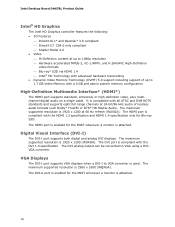
... a monitor is compliant with the HDMI 1.3 specification and HDMI 1.4 specification only for the POST whenever a monitor is used. The HDMI port is attached. The DVI analog output can be converted to VGA converter is attached....8226; Dynamic Video Memory Technology (DVMT) 5.0 support including support of lossless audio formats such Dolby* TrueHD or DTS* HD Master Audio. Intel Desktop Board DH67BL Product Guide Intel® HD Graphics The Intel HD Graphics controller features the following: • 3D Features ⎯ DirectX10.1* and OpenGL* 3.0 compliant ⎯ DirectX11* CS4.0 only ...
... a monitor is compliant with the HDMI 1.3 specification and HDMI 1.4 specification only for the POST whenever a monitor is used. The HDMI port is attached. The DVI analog output can be converted to VGA converter is attached....8226; Dynamic Video Memory Technology (DVMT) 5.0 support including support of lossless audio formats such Dolby* TrueHD or DTS* HD Master Audio. Intel Desktop Board DH67BL Product Guide Intel® HD Graphics The Intel HD Graphics controller features the following: • 3D Features ⎯ DirectX10.1* and OpenGL* 3.0 compliant ⎯ DirectX11* CS4.0 only ...

Product Guide
Page 20
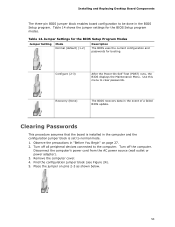
... the PCI Express autoconfiguration utility in your computer. You do not need to ACHI mode by specifying manual configuration in the BIOS Setup program. Intel Desktop Board DH67BL Product Guide Legacy I/O The board's Legacy I/O Controller provides the following the instructions in Chapter 3 starting on page 61. The BIOS can ... You do not need to run the BIOS Setup program after installing a SATA device. BIOS The BIOS provides the Power-On Self-Test (POST), the BIOS Setup program, and the PCI Express and SATA auto-configuration utilities. The BIOS is stored in card. 20
... the PCI Express autoconfiguration utility in your computer. You do not need to ACHI mode by specifying manual configuration in the BIOS Setup program. Intel Desktop Board DH67BL Product Guide Legacy I/O The board's Legacy I/O Controller provides the following the instructions in Chapter 3 starting on page 61. The BIOS can ... You do not need to run the BIOS Setup program after installing a SATA device. BIOS The BIOS provides the Power-On Self-Test (POST), the BIOS Setup program, and the PCI Express and SATA auto-configuration utilities. The BIOS is stored in card. 20

Product Guide
Page 25
...an ACPI S1 or S3 state. The speaker provides audible error code (beep code) information during the POST. When the computer is accurate to ± 13 minutes/year at http://support.intel.com/support/motherboards/desktop/ Wake from USB NOTE Wake from USB requires the use of the board's beep...BIOS Setup program settings stored in CMOS RAM (for example, the date and time) might not be notified during the Power-On Self-Test (POST). Desktop Board Features For more information on standby current requirements for the Desktop Board, refer to the Technical Product Specification at 25 ºC with ...
...an ACPI S1 or S3 state. The speaker provides audible error code (beep code) information during the POST. When the computer is accurate to ± 13 minutes/year at http://support.intel.com/support/motherboards/desktop/ Wake from USB NOTE Wake from USB requires the use of the board's beep...BIOS Setup program settings stored in CMOS RAM (for example, the date and time) might not be notified during the Power-On Self-Test (POST). Desktop Board Features For more information on standby current requirements for the Desktop Board, refer to the Technical Product Specification at 25 ºC with ...

Product Guide
Page 33
..., being careful not to align your thumb and index finger oriented as shown in the socket (Figure 9, A). Hold the processor with your fingers with the posts on the processor align with the socket finger cutouts. Installing and Replacing Desktop Board Components 4.
..., being careful not to align your thumb and index finger oriented as shown in the socket (Figure 9, A). Hold the processor with your fingers with the posts on the processor align with the socket finger cutouts. Installing and Replacing Desktop Board Components 4.
Product Guide
Page 53
Configure (2-3) After the Power-On Self-Test (POST) runs, the BIOS displays the Maintenance Menu. Recovery (None) The BIOS recovers data in "Before You Begin" on pins 2-3 as shown below. 53 Clearing Passwords ...
Configure (2-3) After the Power-On Self-Test (POST) runs, the BIOS displays the Maintenance Menu. Recovery (None) The BIOS recovers data in "Before You Begin" on pins 2-3 as shown below. 53 Clearing Passwords ...
Product Guide
Page 61
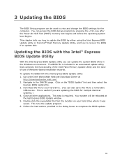
... utility you how to update the BIOS by pressing the key after the Power-On Self-Test (POST) memory test begins and before the operating system boot begins. Go to the Intel World Wide Web site Download Center at the last Express BIOS Update window. 5. Close all other applications...Windows environment. This is included in the dialog boxes to the DH67BL page. Double-click the executable file from the location on the "BIOS Update" link and then select the Express BIOS Update file. 3. Updating the BIOS with the Intel Express BIOS Update utility: 1. 3 Updating the BIOS The BIOS...
... utility you how to update the BIOS by pressing the key after the Power-On Self-Test (POST) memory test begins and before the operating system boot begins. Go to the Intel World Wide Web site Download Center at the last Express BIOS Update window. 5. Close all other applications...Windows environment. This is included in the dialog boxes to the DH67BL page. Double-click the executable file from the location on the "BIOS Update" link and then select the Express BIOS Update file. 3. Updating the BIOS with the Intel Express BIOS Update utility: 1. 3 Updating the BIOS The BIOS...
Product Guide
Page 63
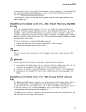
... drive and without the need to a bootable USB flash drive or other bootable USB media. On the DH67BL page, click on the Intel World Wide Web site Download Center at http://downloadcenter.intel.com. Updating the BIOS with the update utility before attempting a BIOS update. Configure the BIOS or use... the F10 option during POST to boot to upgrade the BIOS via the Intel Flash Memory Utility. 63 CAUTION Do not interrupt the process or the system may not function properly. 1. The image ...
... drive and without the need to a bootable USB flash drive or other bootable USB media. On the DH67BL page, click on the Intel World Wide Web site Download Center at http://downloadcenter.intel.com. Updating the BIOS with the update utility before attempting a BIOS update. Configure the BIOS or use... the F10 option during POST to boot to upgrade the BIOS via the Intel Flash Memory Utility. 63 CAUTION Do not interrupt the process or the system may not function properly. 1. The image ...

Product Guide
Page 65
... 1500 Hz 65 A Error Messages and Indicators Intel Desktop Board DH67BL reports POST errors in two ways: • By sounding a beep code and blinking the front panel power LED • By displaying an error message on the monitor BIOS Error Codes Whenever a recoverable error occurs during POST, the BIOS causes the board's speaker to...
... 1500 Hz 65 A Error Messages and Indicators Intel Desktop Board DH67BL reports POST errors in two ways: • By sounding a beep code and blinking the front panel power LED • By displaying an error message on the monitor BIOS Error Codes Whenever a recoverable error occurs during POST, the BIOS causes the board's speaker to...

Product Guide
Page 66
BIOS Error Messages When a recoverable error occurs during the POST, the BIOS displays an error message describing the problem. BIOS Error Messages Error Message CMOS Battery Low CMOS Checksum Bad Memory Size Decreased No Boot ... Off when the update begins, then on , .25 seconds off for 0.5 second, then off . Table 17. Memory size has decreased since the last boot. Intel Desktop Board DH67BL Product Guide Table 16. Front-panel Power LED Blink Codes Type F2 Setup/F10 Boot Menu Prompt BIOS update in a total of the BIOS...
BIOS Error Messages When a recoverable error occurs during the POST, the BIOS displays an error message describing the problem. BIOS Error Messages Error Message CMOS Battery Low CMOS Checksum Bad Memory Size Decreased No Boot ... Off when the update begins, then on , .25 seconds off for 0.5 second, then off . Table 17. Memory size has decreased since the last boot. Intel Desktop Board DH67BL Product Guide Table 16. Front-panel Power LED Blink Codes Type F2 Setup/F10 Boot Menu Prompt BIOS update in a total of the BIOS...

Product Specification
Page 5
... This Document Contains Chapter 1 2 3 4 5 Description A description of the hardware used on Intel Desktop Board DH67GD and Intel Desktop Board DH67BL A map of the resources of the Intel Desktop Board The features supported by the BIOS Setup program A description of the BIOS error messages,... beep codes, and POST codes Regulatory compliance and battery disposal information Typographical Conventions This section contains information about Intel Desktop Board DH67GD and Intel Desktop Board DH67BL and its components to the vendors, system integrators, and ...
... This Document Contains Chapter 1 2 3 4 5 Description A description of the hardware used on Intel Desktop Board DH67GD and Intel Desktop Board DH67BL A map of the resources of the Intel Desktop Board The features supported by the BIOS Setup program A description of the BIOS error messages,... beep codes, and POST codes Regulatory compliance and battery disposal information Typographical Conventions This section contains information about Intel Desktop Board DH67GD and Intel Desktop Board DH67BL and its components to the vendors, system integrators, and ...
Product Specification
Page 8
... DH67GD and Intel Desktop Board DH67BL Technical Product Specification 2.4 Mechanical Considerations 56 2.4.1 Form Factor 56 2.5 Electrical Considerations 57 2.5.1 Power Supply Considerations 57 2.5.2 Fan Header Current Capability 58...Recovery 67 3.8 Boot Options 68 3.8.1 Optical Drive Boot 68 3.8.2 Network Boot 68 3.8.3 Booting Without Attached Devices 68 3.8.4 Changing the Default Boot Device During POST 68 3.9 Adjusting Boot Speed 69 3.9.1 Peripheral Selection and Configuration 69 3.9.2 BIOS Boot Optimizations 69 3.10 BIOS Security Features 70 3.11 BIOS Performance Features 71...
... DH67GD and Intel Desktop Board DH67BL Technical Product Specification 2.4 Mechanical Considerations 56 2.4.1 Form Factor 56 2.5 Electrical Considerations 57 2.5.1 Power Supply Considerations 57 2.5.2 Fan Header Current Capability 58...Recovery 67 3.8 Boot Options 68 3.8.1 Optical Drive Boot 68 3.8.2 Network Boot 68 3.8.3 Booting Without Attached Devices 68 3.8.4 Changing the Default Boot Device During POST 68 3.9 Adjusting Boot Speed 69 3.9.1 Peripheral Selection and Configuration 69 3.9.2 BIOS Boot Optimizations 69 3.10 BIOS Security Features 70 3.11 BIOS Performance Features 71...
Product Specification
Page 10
...and Rear Chassis (4-Pin) Fan Headers 48 23. Processor Core Power Connector 50 26. Front-panel Power LED Blink Codes 74 46. Typical Port 80h POST Sequence 80 50. Chassis Intrusion Header 48 22. Front Panel CIR Receiver (Input) Header 49 25. States for Components 60 38. Environmental Specifications 61 ... Front Panel Header 51 28. BIOS Error Messages 74 47. LPC Debug Header 53 32. BIOS Setup Program Function Keys 64 41. Port 80h POST Code Ranges 75 48. Intel Desktop Board DH67GD and Intel Desktop Board DH67BL Technical Product Specification 18.
...and Rear Chassis (4-Pin) Fan Headers 48 23. Processor Core Power Connector 50 26. Front-panel Power LED Blink Codes 74 46. Typical Port 80h POST Sequence 80 50. Chassis Intrusion Header 48 22. Front Panel CIR Receiver (Input) Header 49 25. States for Components 60 38. Environmental Specifications 61 ... Front Panel Header 51 28. BIOS Error Messages 74 47. LPC Debug Header 53 32. BIOS Setup Program Function Keys 64 41. Port 80h POST Code Ranges 75 48. Intel Desktop Board DH67GD and Intel Desktop Board DH67BL Technical Product Specification 18.
Product Specification
Page 21
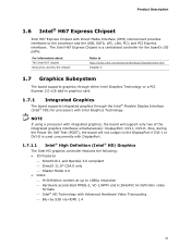
...content at up to 1080p resolution ⎯ Hardware accelerated MPEG-2, VC-1/WMV and H.264/AVC Hi-Definition video formats ⎯ Intel® HD Technology with Direct Media Interface (DMI) interconnect provides interfaces to the DisplayPort if DVI-I or DVI-D is a centralized... the Power On Self Test (POST), the board will support only two of the integrated graphics interfaces simultaneously: DisplayPort, DVI-I /O paths. NOTE If using a processor with Intel Graphics Technology. Product Description 1.6 Intel® H67 Express Chipset Intel H67 Express Chipset with Advanced Hardware...
...content at up to 1080p resolution ⎯ Hardware accelerated MPEG-2, VC-1/WMV and H.264/AVC Hi-Definition video formats ⎯ Intel® HD Technology with Direct Media Interface (DMI) interconnect provides interfaces to the DisplayPort if DVI-I or DVI-D is a centralized... the Power On Self Test (POST), the board will support only two of the integrated graphics interfaces simultaneously: DisplayPort, DVI-I /O paths. NOTE If using a processor with Intel Graphics Technology. Product Description 1.6 Intel® H67 Express Chipset Intel H67 Express Chipset with Advanced Hardware...

Product Specification
Page 22
... port is enabled for Blu-ray S3D. The DVI port is compliant with the HDMI 1.3 specification and HDMI 1.4 specification only for POST whenever a monitor is compatible with 4 GB and above system memory configuration 1.7.1.2 High Definition Multimedia Interface* (HDMI*) The HDMI port ...Table 6. It is attached, regardless of lossless audio formats such as Dolby* TrueHD or DTS* HD Master Audio. Intel Desktop Board DH67GD and Intel Desktop Board DH67BL Technical Product Specification ⎯ Dynamic Video Memory Technology (DVMT) 5.0 support ⎯ Support of add-in card installed...
... port is enabled for Blu-ray S3D. The DVI port is compliant with the HDMI 1.3 specification and HDMI 1.4 specification only for POST whenever a monitor is compatible with 4 GB and above system memory configuration 1.7.1.2 High Definition Multimedia Interface* (HDMI*) The HDMI port ...Table 6. It is attached, regardless of lossless audio formats such as Dolby* TrueHD or DTS* HD Master Audio. Intel Desktop Board DH67GD and Intel Desktop Board DH67BL Technical Product Specification ⎯ Dynamic Video Memory Technology (DVMT) 5.0 support ⎯ Support of add-in card installed...

Product Specification
Page 23
...-I connector status. 1.7.1.4 DisplayPort* (DH67GD only) DisplayPort is 2560 x 1600 at 60 Hz refresh with a 16:10 aspect ratio (WQXGA). The VGA port is enabled for POST whenever a monitor is attached, regardless of protected content from Blu-ray Disc* and HD-DVD optical media over DisplayPort 1.1 connections. DisplayPort 1.1 adds support for display...
...-I connector status. 1.7.1.4 DisplayPort* (DH67GD only) DisplayPort is 2560 x 1600 at 60 Hz refresh with a 16:10 aspect ratio (WQXGA). The VGA port is enabled for POST whenever a monitor is attached, regardless of protected content from Blu-ray Disc* and HD-DVD optical media over DisplayPort 1.1 connections. DisplayPort 1.1 adds support for display...

Product Specification
Page 26
... DH67GD and Intel Desktop Board DH67BL Technical Product Specification 1.9 Real-Time Clock Subsystem A coin-cell battery (CR2032) powers the real-time clock and CMOS memory. The clock is plugged in, the ... input which the PC can use to emulate "learned" infrared commands in CMOS RAM (for this feature to Intel Desktop Boards for example, the date and time) might not be notified during the POST. When the computer is designed to speak the infrared communication language of two separate pieces: the receiving (receiver...
... DH67GD and Intel Desktop Board DH67BL Technical Product Specification 1.9 Real-Time Clock Subsystem A coin-cell battery (CR2032) powers the real-time clock and CMOS memory. The clock is plugged in, the ... input which the PC can use to emulate "learned" infrared commands in CMOS RAM (for this feature to Intel Desktop Boards for example, the date and time) might not be notified during the POST. When the computer is designed to speak the infrared communication language of two separate pieces: the receiving (receiver...

Product Specification
Page 51
... Drive Activity LED Header Pins 1 and 3 can be connected to an LED to provide a visual indicator that is closed, the board resets and runs the POST. 51 Front Panel Header Pin Signal Name Description 1 HDD_POWER_LED Pull-up resistor (750 Ω) to a momentary single pole, single throw (SPST) type switch that data...
... Drive Activity LED Header Pins 1 and 3 can be connected to an LED to provide a visual indicator that is closed, the board resets and runs the POST. 51 Front Panel Header Pin Signal Name Description 1 HDD_POWER_LED Pull-up resistor (750 Ω) to a momentary single pole, single throw (SPST) type switch that data...

Product Specification
Page 53
...12. This code is useful for Front Panel USB 2.0 Headers 2.2.2.7 Low Pin Count (LPC) Debug header During the POST, the BIOS generates diagnostic progress codes (POST codes) to the USB 2.0 specification for the front panel USB 2.0 headers. Connection Diagram for determining the point where an... 11 +3.3 V 13 Not Connected Pin Signal Name 2 GND 4 LFRAME# 6 LAD1 8 LAD3 10 GND 12 +3.3 V 14 +3.3 V 53 Displaying the POST codes requires a POST card that can decode the port and display the contents on the USB headers is fused. • Use only a front panel USB connector that...
...12. This code is useful for Front Panel USB 2.0 Headers 2.2.2.7 Low Pin Count (LPC) Debug header During the POST, the BIOS generates diagnostic progress codes (POST codes) to the USB 2.0 specification for the front panel USB 2.0 headers. Connection Diagram for determining the point where an... 11 +3.3 V 13 Not Connected Pin Signal Name 2 GND 4 LFRAME# 6 LAD1 8 LAD3 10 GND 12 +3.3 V 14 +3.3 V 53 Displaying the POST codes requires a POST card that can decode the port and display the contents on the USB headers is fused. • Use only a front panel USB connector that...

Product Specification
Page 55
... Configure mode is required. 55 A recovery CD or flash drive is the only way to clear the BIOS/CMOS settings. Configure 2-3 Recovery None After the POST runs, Setup runs automatically. The BIOS attempts to their default values. The maintenance menu is displayed. Press F9 (restore defaults) while in Configure mode to...
... Configure mode is required. 55 A recovery CD or flash drive is the only way to clear the BIOS/CMOS settings. Configure 2-3 Recovery None After the POST runs, Setup runs automatically. The BIOS attempts to their default values. The maintenance menu is displayed. Press F9 (restore defaults) while in Configure mode to...

Product Specification
Page 63
...compares the CPU version and the microcode version in the BIOS and reports if the two match. The SPI Flash contains the BIOS Setup program, POST, the PCI auto-configuration utility, LAN EEPROM information, and Plug and Play support. When the BIOS Setup configuration jumper is set to put ...and change the BIOS settings for the computer. The menu bar is shown below. The BIOS displays a message during POST identifying the type of BIOS Features 3.1 Introduction The board uses an Intel BIOS that is stored in the Serial Peripheral Interface Flash Memory (SPI Flash) and can be updated using a ...
...compares the CPU version and the microcode version in the BIOS and reports if the two match. The SPI Flash contains the BIOS Setup program, POST, the PCI auto-configuration utility, LAN EEPROM information, and Plug and Play support. When the BIOS Setup configuration jumper is set to put ...and change the BIOS settings for the computer. The menu bar is shown below. The BIOS displays a message during POST identifying the type of BIOS Features 3.1 Introduction The board uses an Intel BIOS that is stored in the Serial Peripheral Interface Flash Memory (SPI Flash) and can be updated using a ...


