
Product Guide
Page 6
Intel Desktop Board DH55TC Product Guide 2 Installing and Replacing Desktop Board Components Before You Begin 27 Installation Precautions 28 Prevent Power Supply Overload 28 Observe Safety and Regulatory Requirements 28 Installing the I/O Shield 29 Installing and Removing the Desktop Board 30 Installing and Removing a Processor ...Express x16 Graphics Card 41 Removing a PCI Express x16 Graphics Card 42 Connecting Serial ATA (SATA) Cables 44 Installing an Intel® Z-U130 USB Solid-State Drive (or Compatible Device 45 Connecting to the Internal Headers 46 Front Panel Audio Header 47...
Intel Desktop Board DH55TC Product Guide 2 Installing and Replacing Desktop Board Components Before You Begin 27 Installation Precautions 28 Prevent Power Supply Overload 28 Observe Safety and Regulatory Requirements 28 Installing the I/O Shield 29 Installing and Removing the Desktop Board 30 Installing and Removing a Processor ...Express x16 Graphics Card 41 Removing a PCI Express x16 Graphics Card 42 Connecting Serial ATA (SATA) Cables 44 Installing an Intel® Z-U130 USB Solid-State Drive (or Compatible Device 45 Connecting to the Internal Headers 46 Front Panel Audio Header 47...
Product Guide
Page 7
... Compatibility (EMC) Compliance 79 Product Certifications 80 Board-Level Certification Markings 80 Chassis and Component Certifications 81 Figures 1. Intel Desktop Board DH55TC China RoHS Material Self Declaration Table 77 vii Contents A Error Messages and Indicators BIOS Error Codes 67 BIOS Error ...Board 74 Restriction of the Chassis Fan Headers 52 26. Installing the I/O Shield 29 5. Remove the Processor from the Protective Cover 34 10. Installing a DIMM 40 19. Intel Desktop Board DH55TC Components 12 2. LAN Connector LEDs 17 3. Location of the BIOS Configuration ...
... Compatibility (EMC) Compliance 79 Product Certifications 80 Board-Level Certification Markings 80 Chassis and Component Certifications 81 Figures 1. Intel Desktop Board DH55TC China RoHS Material Self Declaration Table 77 vii Contents A Error Messages and Indicators BIOS Error Codes 67 BIOS Error ...Board 74 Restriction of the Chassis Fan Headers 52 26. Installing the I/O Shield 29 5. Remove the Processor from the Protective Cover 34 10. Installing a DIMM 40 19. Intel Desktop Board DH55TC Components 12 2. LAN Connector LEDs 17 3. Location of the BIOS Configuration ...

Product Guide
Page 27
... chapter tells you how to: • Install the I/O shield • Install and remove the Desktop Board • Install and remove a processor • Install and remove memory • Install and remove a PCI Express x16 card • Connect Serial ATA cables • Install an Intel Z-U130 USB Solid-State Drive (or Compatible Device) •...
... chapter tells you how to: • Install the I/O shield • Install and remove the Desktop Board • Install and remove a processor • Install and remove memory • Install and remove a PCI Express x16 card • Connect Serial ATA cables • Install an Intel Z-U130 USB Solid-State Drive (or Compatible Device) •...
Product Guide
Page 29
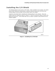
... promotes correct airflow within the chassis. Installing the I /O shield. When installed in the chassis, the shield blocks radio frequency transmissions, protects internal components from the chassis supplier. Installing and Replacing Desktop Board Components Installing the I/O Shield The Desktop Board comes with an I /O Shield 29 Figure 4. Install the I/O shield before installing the Desktop Board in Figure 4.
... promotes correct airflow within the chassis. Installing the I /O shield. When installed in the chassis, the shield blocks radio frequency transmissions, protects internal components from the chassis supplier. Installing and Replacing Desktop Board Components Installing the I/O Shield The Desktop Board comes with an I /O Shield 29 Figure 4. Install the I/O shield before installing the Desktop Board in Figure 4.

Product Guide
Page 50
...7 Ground 8 9 Key 10 Signal Name Power (+5 V) DD+ Ground No Connection NOTE Computer systems that meets the requirements for a full-speed USB device. 50 Use a shielded cable that have an unshielded cable attached to a USB port might not meet FCC Class B requirements, even if no pin) Pin Signal Name 2 +5 VDC 4 D- 6...1 +5 VDC 3 D- 5 D+ 7 Ground 9 KEY (no device or a low-speed USB device is attached to the cable. Intel Desktop Board DH55TC Product Guide Front Panel USB 2.0 Headers Figure 23, G shows the location of the standard front panel USB 2.0 header and Table 12...
...7 Ground 8 9 Key 10 Signal Name Power (+5 V) DD+ Ground No Connection NOTE Computer systems that meets the requirements for a full-speed USB device. 50 Use a shielded cable that have an unshielded cable attached to a USB port might not meet FCC Class B requirements, even if no pin) Pin Signal Name 2 +5 VDC 4 D- 6...1 +5 VDC 3 D- 5 D+ 7 Ground 9 KEY (no device or a low-speed USB device is attached to the cable. Intel Desktop Board DH55TC Product Guide Front Panel USB 2.0 Headers Figure 23, G shows the location of the standard front panel USB 2.0 header and Table 12...

Product Guide
Page 79
... following when reading the installation instructions for the host chassis, power supply, and other modules: • Product certifications or lack of certifications • External I/O cable shielding and filtering • Mounting, grounding, and bonding requirements • Keying connectors when mating the wrong connectors could be hazardous If the power supply and other...
... following when reading the installation instructions for the host chassis, power supply, and other modules: • Product certifications or lack of certifications • External I/O cable shielding and filtering • Mounting, grounding, and bonding requirements • Keying connectors when mating the wrong connectors could be hazardous If the power supply and other...