
Product Specification
Page 5
... Board Layout 12 1.2.4 Block Diagram 14 1.3 Online Support ...15 1.4 Processor ...15 1.5 System Memory ...16 1.5.1 Memory Configurations 17 1.6 Intel® 945P Chipset...21 1.6.1 USB ...21 1.6.2 IDE Support 22 1.6.3 Real-Time Clock, CMOS SRAM, and Battery 23 1.7 PCI Express* Connectors 23 1.8 IEEE-1394a Connectors (Optional 24 1.9 Legacy I/O Controller 24 1.9.1 Serial Port...24 1.9.2 Parallel Port 24 1.9.3 Diskette Drive Controller 25 1.9.4 Keyboard and Mouse Interface 25 1.10 Audio Subsystem ...25 1.10.1 Audio Subsystem Software 25 1.10.2 Audio Connectors 25 1.10.3 6-Channel...
... Board Layout 12 1.2.4 Block Diagram 14 1.3 Online Support ...15 1.4 Processor ...15 1.5 System Memory ...16 1.5.1 Memory Configurations 17 1.6 Intel® 945P Chipset...21 1.6.1 USB ...21 1.6.2 IDE Support 22 1.6.3 Real-Time Clock, CMOS SRAM, and Battery 23 1.7 PCI Express* Connectors 23 1.8 IEEE-1394a Connectors (Optional 24 1.9 Legacy I/O Controller 24 1.9.1 Serial Port...24 1.9.2 Parallel Port 24 1.9.3 Diskette Drive Controller 25 1.9.4 Keyboard and Mouse Interface 25 1.10 Audio Subsystem ...25 1.10.1 Audio Subsystem Software 25 1.10.2 Audio Connectors 25 1.10.3 6-Channel...

Product Specification
Page 7
... Connection Diagram for Omni-directional Airflow 61 25. Processor Heatsink for Front Panel USB Connectors 55 20. Manufacturing Options 11 3. Supported Memory Configurations 16 5. LAN Connector LED States 28 6. Power States and Targeted System Power 33 9. Dual Channel (Interleaved) Mode Configuration with One DIMM 20 8. Location of the Jumper Block 56 22. Board Dimensions...57 23. Localized High Temperature Zones 62 Tables 1. Wake-up Devices and Events 34 vii Dual Channel (Interleaved) Mode Configuration with Four DIMMs 19 7. Dual Channel (Interleaved) Mode...
... Connection Diagram for Omni-directional Airflow 61 25. Processor Heatsink for Front Panel USB Connectors 55 20. Manufacturing Options 11 3. Supported Memory Configurations 16 5. LAN Connector LED States 28 6. Power States and Targeted System Power 33 9. Dual Channel (Interleaved) Mode Configuration with One DIMM 20 8. Location of the Jumper Block 56 22. Board Dimensions...57 23. Localized High Temperature Zones 62 Tables 1. Wake-up Devices and Events 34 vii Dual Channel (Interleaved) Mode Configuration with Four DIMMs 19 7. Dual Channel (Interleaved) Mode...

Product Specification
Page 8
... Panel Audio Connector 50 19. Main Power Connector 51 24. Boot Device Menu Options 73 40. Port 80h POST Code Ranges 78 44. I/O Map ...42 13. Component-side Connectors Shown in Figure 16 47 17. Chassis Intrusion Connector 50 20. Front and Rear Chassis Fan Connectors 50 23. Front Panel Connector 53 27. Environmental Specifications 64 34. BIOS Error Messages 77 43. Auxiliary Front Panel Power/Sleep LED Connector 52 26. BIOS Setup Program Function Keys 70 39. Beep Codes ...77 42. Port 80h POST Codes 79...
... Panel Audio Connector 50 19. Main Power Connector 51 24. Boot Device Menu Options 73 40. Port 80h POST Code Ranges 78 44. I/O Map ...42 13. Component-side Connectors Shown in Figure 16 47 17. Chassis Intrusion Connector 50 20. Front and Rear Chassis Fan Connectors 50 23. Front Panel Connector 53 27. Environmental Specifications 64 34. BIOS Error Messages 77 43. Auxiliary Front Panel Power/Sleep LED Connector 52 26. BIOS Setup Program Function Keys 70 39. Beep Codes ...77 42. Port 80h POST Codes 79...
Product Specification
Page 14
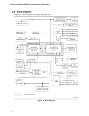
...USB Back Panel/Front Panel USB Ports Legacy I/O Controller LPC Bus Serial Port Parallel Port PS/2 Mouse PS/2 Keyboard Diskette Drive Connector Intel 82801G I/O Controller Hub (ICH7) Serial Peripheral Interface (SPI) Flash Device DMI Interconnect High Definition Audio Link LAN Connect Interface Channel A DIMMs (2) Dual-Channel Memory Bus SMBus Channel B DIMMs (2) IEEE-1394a Connectors (Optional) IEEE-1394a Controller (Optional) PCI Bus PCI Bus PCI Slot 1 PCI Slot 2 SMBus Hardware Monitoring and Fan Control ASIC LPC TPM Component Bus (Optional) 10/100 LAN PLC (Optional) LAN...
...USB Back Panel/Front Panel USB Ports Legacy I/O Controller LPC Bus Serial Port Parallel Port PS/2 Mouse PS/2 Keyboard Diskette Drive Connector Intel 82801G I/O Controller Hub (ICH7) Serial Peripheral Interface (SPI) Flash Device DMI Interconnect High Definition Audio Link LAN Connect Interface Channel A DIMMs (2) Dual-Channel Memory Bus SMBus Channel B DIMMs (2) IEEE-1394a Connectors (Optional) IEEE-1394a Controller (Optional) PCI Bus PCI Bus PCI Slot 1 PCI Slot 2 SMBus Hardware Monitoring and Fan Control ASIC LPC TPM Component Bus (Optional) 10/100 LAN PLC (Optional) LAN...
Product Specification
Page 40
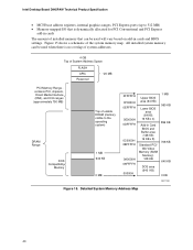
... amount of installed memory that can be used will vary based on add-in Card BIOS and Buffer area (128 KB; 16 KB x 8) Standard PCI/ ISA Video Memory (SMM Memory) 128 KB DOS area (640 KB) 1 MB 960 KB 896 KB 768 KB 640 KB 0 KB OM17140 Figure 15. Intel Desktop Board D945PAW Technical Product Specification • MCH base address registers, internal graphics ranges, PCI Express ports (up to...
... amount of installed memory that can be used will vary based on add-in Card BIOS and Buffer area (128 KB; 16 KB x 8) Standard PCI/ ISA Video Memory (SMM Memory) 128 KB DOS area (640 KB) 1 MB 960 KB 896 KB 768 KB 640 KB 0 KB OM17140 Figure 15. Intel Desktop Board D945PAW Technical Product Specification • MCH base address registers, internal graphics ranges, PCI Express ports (up to...

Product Specification
Page 43
...00 00 Description Memory controller of Intel 82945P component PCI Express x16 graphics port (Note 1) Intel High Definition Audio Controller PCI Express port 1 PCI Express port 2 PCI Express port 3 PCI Express port 4 USB UHCI controller 1 USB UHCI controller 2 USB UHCI controller 3 USB UHCI controller 4 EHCI controller PCI bridge PCI controller Parallel ATA IDE controller Serial ATA controller SMBus controller Gigabit LAN controller (if present) PCI Conventional bus connector 1 PCI Conventional bus connector 2 Intel 82562 10/100 Mbits/sec LAN PLC (if present) PCI Express video controller (Note...
...00 00 Description Memory controller of Intel 82945P component PCI Express x16 graphics port (Note 1) Intel High Definition Audio Controller PCI Express port 1 PCI Express port 2 PCI Express port 3 PCI Express port 4 USB UHCI controller 1 USB UHCI controller 2 USB UHCI controller 3 USB UHCI controller 4 EHCI controller PCI bridge PCI controller Parallel ATA IDE controller Serial ATA controller SMBus controller Gigabit LAN controller (if present) PCI Conventional bus connector 1 PCI Conventional bus connector 2 Intel 82562 10/100 Mbits/sec LAN PLC (if present) PCI Express video controller (Note...
Product Specification
Page 69
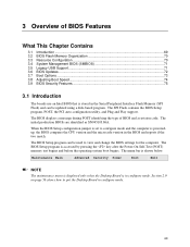
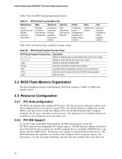
... the BIOS Setup program, POST, the PCI auto-configuration utility, and Plug and Play support. The BIOS Setup program can be used to view and change the BIOS settings for the computer. The menu bar is accessed by pressing the key after the Power-On Self-Test (POST) memory test begins and before the operating system boot begins. When the BIOS Setup configuration jumper is set to put the Desktop Board in the Serial Peripheral Interface Flash Memory (SPI Flash) and can be updated using a disk...
... the BIOS Setup program, POST, the PCI auto-configuration utility, and Plug and Play support. The BIOS Setup program can be used to view and change the BIOS settings for the computer. The menu bar is accessed by pressing the key after the Power-On Self-Test (POST) memory test begins and before the operating system boot begins. When the BIOS Setup configuration jumper is set to put the Desktop Board in the Serial Peripheral Interface Flash Memory (SPI Flash) and can be updated using a disk...
Product Specification
Page 70
... use by the add-in card. 3.3.2 PCI IDE Support If you select Auto in cards. BIOS Setup Program Menu Bar Maintenance Main Advanced Security Clears passwords and displays processor information Displays processor and memory configuration Configures advanced features available through the chipset Sets passwords and security features Power Boot Configures power management features and power supply controls Selects boot options Exit Saves or discards changes to ATA-66/100 and recognizes any ATAPI compliant devices, including CD-ROM drives, tape drives, and Ultra DMA drives. PCI devices...
... use by the add-in card. 3.3.2 PCI IDE Support If you select Auto in cards. BIOS Setup Program Menu Bar Maintenance Main Advanced Security Clears passwords and displays processor information Displays processor and memory configuration Configures advanced features available through the chipset Sets passwords and security features Power Boot Configures power management features and power supply controls Selects boot options Exit Saves or discards changes to ATA-66/100 and recognizes any ATAPI compliant devices, including CD-ROM drives, tape drives, and Ultra DMA drives. PCI devices...
Product Specification
Page 71
... main component of SMBIOS is enabled by specifying manual configuration in a managed network. POST completes. 71 The BIOS supports an SMBIOS table interface for accessing this support, an SMBIOS service-level application running on a non-Plug and Play operating system can obtain the SMBIOS information. 3.5 Legacy USB Support Legacy USB support enables USB devices to be used to access the BIOS Setup program, and to install an operating system that supports USB. When you to an ATAPI CD-ROM drive...
... main component of SMBIOS is enabled by specifying manual configuration in a managed network. POST completes. 71 The BIOS supports an SMBIOS table interface for accessing this support, an SMBIOS service-level application running on a non-Plug and Play operating system can obtain the SMBIOS information. 3.5 Legacy USB Support Legacy USB support enables USB devices to be used to access the BIOS Setup program, and to install an operating system that supports USB. When you to an ATAPI CD-ROM drive...

Product Specification
Page 74
.... 3.8.2 BIOS Boot Optimizations Use of painting complex graphic images and changing video modes. This could save several seconds of the following techniques help improve system boot speed: • Choose a hard drive with parameters such as "power-up to four seconds of option ROM boot time. This can reduce up to the boot process. • Try different monitors. In the Boot Menu: • Set the hard disk drive as logo displays, screen repaints, or mode changes in the Drive Configuration...
.... 3.8.2 BIOS Boot Optimizations Use of painting complex graphic images and changing video modes. This could save several seconds of the following techniques help improve system boot speed: • Choose a hard drive with parameters such as "power-up to four seconds of option ROM boot time. This can reduce up to the boot process. • Try different monitors. In the Boot Menu: • Set the hard disk drive as logo displays, screen repaints, or mode changes in the Drive Configuration...

Product Specification
Page 78
...an unrecoverable error. Input devices: Keyboard/Mouse. 9F is an unrecoverable CPU error. BF is no memory detected or no useful memory detected. Boot device selection. Displaying the POST-codes requires a PCI bus add-in PCI bus connector 1. BF C0 - FF Category/Subsystem Debug codes: Can be installed in card, often called a POST card. Recovery: 3F indicated recovery failure. Intel Desktop Board D945PAW Technical Product Specification 4.4 Port 80h POST Codes During the POST, the BIOS generates diagnostic progress codes (POST-codes) to I /O Busses: PCI, USB, ISA, ATA...
...an unrecoverable error. Input devices: Keyboard/Mouse. 9F is an unrecoverable CPU error. BF is no memory detected or no useful memory detected. Boot device selection. Displaying the POST-codes requires a PCI bus add-in PCI bus connector 1. BF C0 - FF Category/Subsystem Debug codes: Can be installed in card, often called a POST card. Recovery: 3F indicated recovery failure. Intel Desktop Board D945PAW Technical Product Specification 4.4 Port 80h POST Codes During the POST, the BIOS generates diagnostic progress codes (POST-codes) to I /O Busses: PCI, USB, ISA, ATA...

Product Specification
Page 79
... the memory controller and the DIMMs Configuring memory Optimizing memory settings Initializing memory, such as ECC init Testing memory PCI Bus Enumerating PCI busses Allocating resources to PCI bus Hot Plug PCI controller initialization Reserved for PCI Bus USB Resetting USB bus Reserved for USB ATA/ATAPI/SATA Resetting PATA/SATA bus and all devices Reserved for ATA SMBus Resetting SMBUS Reserved for SMBUS Local Console Resetting the VGA controller Disabling the VGA controller Enabling the VGA controller Remote Console Resetting the console controller Disabling the console controller Enabling...
... the memory controller and the DIMMs Configuring memory Optimizing memory settings Initializing memory, such as ECC init Testing memory PCI Bus Enumerating PCI busses Allocating resources to PCI bus Hot Plug PCI controller initialization Reserved for PCI Bus USB Resetting USB bus Reserved for USB ATA/ATAPI/SATA Resetting PATA/SATA bus and all devices Reserved for ATA SMBus Resetting SMBUS Reserved for SMBUS Local Console Resetting the VGA controller Disabling the VGA controller Enabling the VGA controller Remote Console Resetting the console controller Disabling the console controller Enabling...
English Product Guide
Page 3
... requirements for Intel® Desktop Board D945PAW. The suitability of this manual: CAUTION Cautions warn the user about how to prevent damage to hardware or loss of product features 2 Installing and Replacing Desktop Board Components: instructions on how to install the desktop board and other environments, such as medical, industrial, alarm systems, test equipment, etc. Preface This Product Guide gives information about BIOS error messages and beep codes B Regulatory...
... requirements for Intel® Desktop Board D945PAW. The suitability of this manual: CAUTION Cautions warn the user about how to prevent damage to hardware or loss of product features 2 Installing and Replacing Desktop Board Components: instructions on how to install the desktop board and other environments, such as medical, industrial, alarm systems, test equipment, etc. Preface This Product Guide gives information about BIOS error messages and beep codes B Regulatory...
English Product Guide
Page 12
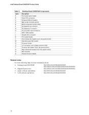
... power connector (2x12) BIOS configuration jumper block PCI Express x16 connector PCI Express x1 connector PCI bus add-in card connectors IEEE 1394a headers Diskette drive connector Front panel header Front chassis fan header (3-pin, fan speed control) Alternate power LED header Processor socket 12 V processor core voltage connector (2x2) Processor fan header (4-pin, fan speed control) Rear chassis fan header (3-pin, fan speed control) IDE connector Chassis intrusion header Related Links: Go to the following links for more information about: • Desktop board D945PAW http://www.intel...
... power connector (2x12) BIOS configuration jumper block PCI Express x16 connector PCI Express x1 connector PCI bus add-in card connectors IEEE 1394a headers Diskette drive connector Front panel header Front chassis fan header (3-pin, fan speed control) Alternate power LED header Processor socket 12 V processor core voltage connector (2x2) Processor fan header (4-pin, fan speed control) Rear chassis fan header (3-pin, fan speed control) IDE connector Chassis intrusion header Related Links: Go to the following links for more information about: • Desktop board D945PAW http://www.intel...
English Product Guide
Page 18
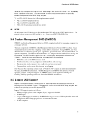
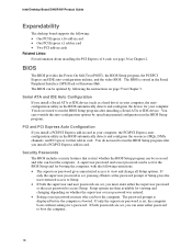
... installing the PCI Express x16 card, see page 36 in card. PCI and PCI Express Auto Configuration If you install a PCI/PCI Express add-in card in Chapter 3. If only the supervisor password is booted. Serial ATA and IDE Auto Configuration If you must enter either password to boot the computer. 18 Setup options are set , you install a Serial ATA or IDE device (such as a hard drive) in your computer, the autoconfiguration utility in the BIOS automatically detects and configures the device for your computer, the PCI/PCI Express autoconfiguration utility...
... installing the PCI Express x16 card, see page 36 in card. PCI and PCI Express Auto Configuration If you install a PCI/PCI Express add-in card in Chapter 3. If only the supervisor password is booted. Serial ATA and IDE Auto Configuration If you must enter either password to boot the computer. 18 Setup options are set , you install a Serial ATA or IDE device (such as a hard drive) in your computer, the autoconfiguration utility in the BIOS automatically detects and configures the device for your computer, the PCI/PCI Express autoconfiguration utility...
English Product Guide
Page 20
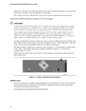
... menu: http://support.intel.com/support/motherboards/desktop/ 20 If the standby current necessary to any controlled chassis fan header. Power supplies used with this feature can damage the power supply and/or effect ACPI S3 sleep state functionality. Instantly Available PC technology enables the board to enter the ACPI S3 (Suspend-to its last known awake state. Location of delivering adequate +5 V standby current. Intel Desktop Board D945PAW Product Guide operating at full speed. This includes the memory modules and PCI bus connectors...
... menu: http://support.intel.com/support/motherboards/desktop/ 20 If the standby current necessary to any controlled chassis fan header. Power supplies used with this feature can damage the power supply and/or effect ACPI S3 sleep state functionality. Instantly Available PC technology enables the board to enter the ACPI S3 (Suspend-to its last known awake state. Location of delivering adequate +5 V standby current. Intel Desktop Board D945PAW Product Guide operating at full speed. This includes the memory modules and PCI bus connectors...

English Product Guide
Page 23
...and from any telecommunications links, networks, or modems before you how to: • Install the I/O shield • Install and remove the desktop board • Install and remove a processor and memory • Install and remove a PCI Express x16 card • Connect the IDE and Serial ATA cables • Connect internal headers • Set up flexible 6-channel audio with jack re-tasking • Connect fans and power cables • Locate other connectors • Set the BIOS configuration jumper • Clear passwords • Replace the battery Before You Begin CAUTIONS The procedures...
...and from any telecommunications links, networks, or modems before you how to: • Install the I/O shield • Install and remove the desktop board • Install and remove a processor and memory • Install and remove a PCI Express x16 card • Connect the IDE and Serial ATA cables • Connect internal headers • Set up flexible 6-channel audio with jack re-tasking • Connect fans and power cables • Locate other connectors • Set the BIOS configuration jumper • Clear passwords • Replace the battery Before You Begin CAUTIONS The procedures...
English Product Guide
Page 42
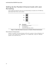
and 6-channel audio configurations. For 6-channel audio, connect two additional speakers to the rear left /right out Center/LFE (Subwoofer) or Mic In Figure 21. Back Panel Audio Connectors for Flexible 6-Channel Audio System Multi-Channel Analog Audio Connect two speakers to the front left/right out (B) and two speakers to the center LFE out (C). 42 Intel Desktop Board D945PAW Product Guide Setting Up the Flexible 6-Channel Audio with Jack Re-tasking After installing the SigmaTel audio driver from...
and 6-channel audio configurations. For 6-channel audio, connect two additional speakers to the rear left /right out Center/LFE (Subwoofer) or Mic In Figure 21. Back Panel Audio Connectors for Flexible 6-Channel Audio System Multi-Channel Analog Audio Connect two speakers to the front left/right out (B) and two speakers to the center LFE out (C). 42 Intel Desktop Board D945PAW Product Guide Setting Up the Flexible 6-Channel Audio with Jack Re-tasking After installing the SigmaTel audio driver from...

English Product Guide
Page 47
... AC power source. 11. Place the jumper on pins 1-2 as shown below . 1 3 13. Replace the cover, plug in the computer and the configuration jumper block is set to select Clear Passwords. Use the arrow keys to normal mode. 1. Press and Setup displays a pop-up screen requesting that the board is installed in the computer, and turn on page 23. 2. Installing and Replacing Desktop Board Components Clearing Passwords This procedure assumes that you confirm clearing the password. Remove the...
... AC power source. 11. Place the jumper on pins 1-2 as shown below . 1 3 13. Replace the cover, plug in the computer and the configuration jumper block is set to select Clear Passwords. Use the arrow keys to normal mode. 1. Press and Setup displays a pop-up screen requesting that the board is installed in the computer, and turn on page 23. 2. Installing and Replacing Desktop Board Components Clearing Passwords This procedure assumes that you confirm clearing the password. Remove the...
Simplified Chinese Product Guide
Page 10
... • 4 Mbit SMBIOS • Intel® Rapid BIOS Boot BIOS Intel® Express BIOS Update BIOS 更新) 电源管理 ACPI RAM (STR) • USB、PCI、PCI Express、PS/2、LAN 硬件管理 Intel® Precision Cooling Technology D945PAW TPS)、BIOS http://support.intel.com/support/motherboards/desktop/ Microsoft Windows* 2000 • Microsoft Windows XP Professional • Microsoft Windows XP Professional x64 Edition • Microsoft Windows XP Home • Microsoft...
... • 4 Mbit SMBIOS • Intel® Rapid BIOS Boot BIOS Intel® Express BIOS Update BIOS 更新) 电源管理 ACPI RAM (STR) • USB、PCI、PCI Express、PS/2、LAN 硬件管理 Intel® Precision Cooling Technology D945PAW TPS)、BIOS http://support.intel.com/support/motherboards/desktop/ Microsoft Windows* 2000 • Microsoft Windows XP Professional • Microsoft Windows XP Professional x64 Edition • Microsoft Windows XP Home • Microsoft...


