Product Guide
Page 5
Contents 1 Desktop Board Features Desktop Board Components 12 Processor ...14 System Memory 14 Mobile Intel® 945GSE Express Chipset 14 Intel 945GSE Graphics Subsystem 15 Operating System Support 16 Onboard Audio Subsystem 16 Legacy Input/Output (I/O) Controller 17 ... 20 Security Passwords 21 Power Management Features 22 ACPI ...22 Hardware Support 22 ENERGY STAR*, e-Standby, and EuP Compliance 25 Battery ...25 Real-Time Clock 25 2 Installing and Replacing Desktop Board Components Before You Begin 27 Installation Precautions 28 Prevent Power Supply Overload 28 Observe ...
Contents 1 Desktop Board Features Desktop Board Components 12 Processor ...14 System Memory 14 Mobile Intel® 945GSE Express Chipset 14 Intel 945GSE Graphics Subsystem 15 Operating System Support 16 Onboard Audio Subsystem 16 Legacy Input/Output (I/O) Controller 17 ... 20 Security Passwords 21 Power Management Features 22 ACPI ...22 Hardware Support 22 ENERGY STAR*, e-Standby, and EuP Compliance 25 Battery ...25 Real-Time Clock 25 2 Installing and Replacing Desktop Board Components Before You Begin 27 Installation Precautions 28 Prevent Power Supply Overload 28 Observe ...
Product Guide
Page 6
Intel Desktop Board D945GSEJT Product Guide 3 Updating the BIOS Updating the BIOS with the Intel® Express BIOS Update Utility 55 Updating the BIOS with the Iflash Memory Update Utility 56 Obtaining the BIOS Update File 56 Using the Iflash Memory Update Utility 56 Recovering the BIOS 57 A Board Status and Error Messages Front-panel Power LED Blink...
Intel Desktop Board D945GSEJT Product Guide 3 Updating the BIOS Updating the BIOS with the Intel® Express BIOS Update Utility 55 Updating the BIOS with the Iflash Memory Update Utility 56 Obtaining the BIOS Update File 56 Using the Iflash Memory Update Utility 56 Recovering the BIOS 57 A Board Status and Error Messages Front-panel Power LED Blink...
Product Guide
Page 7
...Removing the Battery 53 18. Intel Desktop Board D945GSEJT China RoHS Material Self Declaration Table .........68 Tables 1. Front Panel Audio Header for the BIOS Setup Program Modes 48 24. Intel Desktop Board D945GSEJT Mounting Screw Holes 30 6. Location of the Standby Power Indicator 23 4. Front Panel ... 38 10. Jumper Settings for AC '97 Audio 40 18. Front-panel Power LED Blink and Internal Speaker Beep Codes 59 26. Intel Desktop Board D945GSEJT Components 12 2. Installing an Intel Z-U130 USB Solid-State Drive (or Compatible Device 35 11. Connection Diagram ...
...Removing the Battery 53 18. Intel Desktop Board D945GSEJT China RoHS Material Self Declaration Table .........68 Tables 1. Front Panel Audio Header for the BIOS Setup Program Modes 48 24. Intel Desktop Board D945GSEJT Mounting Screw Holes 30 6. Location of the Standby Power Indicator 23 4. Front Panel ... 38 10. Jumper Settings for AC '97 Audio 40 18. Front-panel Power LED Blink and Internal Speaker Beep Codes 59 26. Intel Desktop Board D945GSEJT Components 12 2. Installing an Intel Z-U130 USB Solid-State Drive (or Compatible Device 35 11. Connection Diagram ...
Product Guide
Page 9
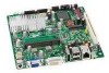
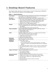
Table 1 summarizes the features of Intel® Desktop Board D945GSEJT. 1 Desktop Board Features This chapter briefly describes the main features of the Desktop Board. Table 1. Feature Summary Form Factor Processor Main Memory Chipset Internal Graphics Audio Expansion Capabilities Peripheral Interfaces Legacy I /O Controller Hub (ICH7-M) Intel® Graphics Media Accelerator 950 (Intel® GMA 950) onboard graphics subsystem with gold-plated contacts •...
Table 1 summarizes the features of Intel® Desktop Board D945GSEJT. 1 Desktop Board Features This chapter briefly describes the main features of the Desktop Board. Table 1. Feature Summary Form Factor Processor Main Memory Chipset Internal Graphics Audio Expansion Capabilities Peripheral Interfaces Legacy I /O Controller Hub (ICH7-M) Intel® Graphics Media Accelerator 950 (Intel® GMA 950) onboard graphics subsystem with gold-plated contacts •...
Product Guide
Page 10
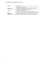
Intel Desktop Board D945GSEJT Product Guide BIOS LAN Support Power Power Management • Intel® BIOS • Support for Advanced Configuration and Power Interface (ACPI), Plug and Play, and SMBIOS • 10/100/1000 Mb/s (Gigabit) Ethernet LAN Subsystem using a RealTek* 8111DL Gigabit Ethernet Controller • Integrated DC-to-DC circuitry • 12 VDC jack on back panel for external...
Intel Desktop Board D945GSEJT Product Guide BIOS LAN Support Power Power Management • Intel® BIOS • Support for Advanced Configuration and Power Interface (ACPI), Plug and Play, and SMBIOS • 10/100/1000 Mb/s (Gigabit) Ethernet LAN Subsystem using a RealTek* 8111DL Gigabit Ethernet Controller • Integrated DC-to-DC circuitry • 12 VDC jack on back panel for external...
Product Guide
Page 14
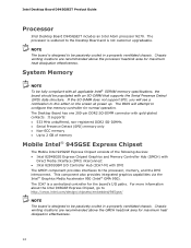
Intel Desktop Board D945GSEJT Product Guide Processor Intel Desktop Board D945GSEJT includes an Intel Atom processor N270. It supports: • 533 MHz unbuffered, non-registered DDR2 SO-DIMMs • Serial Presence Detect (SPD) memory only • Non-ECC memory • Up to 2 GB of memory Mobile Intel® 945GSE Express Chipset The Mobile Intel 945GSE Express Chipset consists of the following devices: • Intel 82945GSE Express Chipset...
Intel Desktop Board D945GSEJT Product Guide Processor Intel Desktop Board D945GSEJT includes an Intel Atom processor N270. It supports: • 533 MHz unbuffered, non-registered DDR2 SO-DIMMs • Serial Presence Detect (SPD) memory only • Non-ECC memory • Up to 2 GB of memory Mobile Intel® 945GSE Express Chipset The Mobile Intel 945GSE Express Chipset consists of the following devices: • Intel 82945GSE Express Chipset...
Product Guide
Page 17
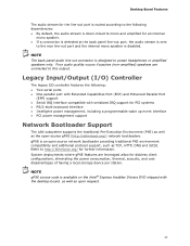
... line-out port and the internal mono speaker is disabled. NOTE gPXE source code is available on the Intel® Express Installer Drivers DVD shipped with serialized IRQ support for PCI systems • PS/2-style keyboard interface • Intelligent...http://etherboot.org/) network bootloaders. Refer to http://etherboot.org/ for diskless client configurations, eliminating the power consumption, thermal, acoustic, and cost disadvantages of having a local storage device per station. Desktop Board Features The audio stream for the line-out port is routed according to the following : •...
... line-out port and the internal mono speaker is disabled. NOTE gPXE source code is available on the Intel® Express Installer Drivers DVD shipped with serialized IRQ support for PCI systems • PS/2-style keyboard interface • Intelligent...http://etherboot.org/) network bootloaders. Refer to http://etherboot.org/ for diskless client configurations, eliminating the power consumption, thermal, acoustic, and cost disadvantages of having a local storage device per station. Desktop Board Features The audio stream for the line-out port is routed according to the following : •...
Product Guide
Page 18
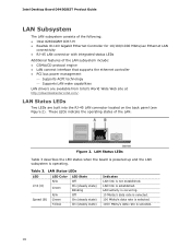
...subsystem include: • CSMA/CD protocol engine • LAN connect interface that supports the ethernet controller • PCI bus power management ⎯ Supports ACPI technology ⎯ Supports LAN wake capabilities LAN drivers are built into the RJ-45 LAN connector ...rate is established. Intel Desktop Board D945GSEJT Product Guide LAN Subsystem The LAN subsystem consists of the following: • Intel 82801GBM ICH7-M • Realtek 8111D Gigabit Ethernet Controller for 10/100/1000 Mbits/sec Ethernet LAN connectivity • RJ-45 LAN connector with integrated status LEDs Additional ...
...subsystem include: • CSMA/CD protocol engine • LAN connect interface that supports the ethernet controller • PCI bus power management ⎯ Supports ACPI technology ⎯ Supports LAN wake capabilities LAN drivers are built into the RJ-45 LAN connector ...rate is established. Intel Desktop Board D945GSEJT Product Guide LAN Subsystem The LAN subsystem consists of the following: • Intel 82801GBM ICH7-M • Realtek 8111D Gigabit Ethernet Controller for 10/100/1000 Mbits/sec Ethernet LAN connectivity • RJ-45 LAN connector with integrated status LEDs Additional ...
Product Guide
Page 19
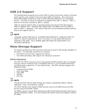
... USB 2.0 Support The Desktop Board supports up to seven USB 2.0 ports (three ports routed to the back panel and four ports routed to USB 1.1 operation. The USB 2.0 ports are backward compatible with 2.5 or 3.5 inch PATA hard drives (including power support for a full-speed USB device. This may be... PATA interface that is accessible through a 44-pin connector that do not support USB 2.0. One of the front panel USB headers supports an Intel Z-U130 USB Solid-State Drive (or compatible device). USB 2.0 support requires both an operating system and drivers that meets the requirements for 2.5...
... USB 2.0 Support The Desktop Board supports up to seven USB 2.0 ports (three ports routed to the back panel and four ports routed to USB 1.1 operation. The USB 2.0 ports are backward compatible with 2.5 or 3.5 inch PATA hard drives (including power support for a full-speed USB device. This may be... PATA interface that is accessible through a 44-pin connector that do not support USB 2.0. One of the front panel USB headers supports an Intel Z-U130 USB Solid-State Drive (or compatible device). USB 2.0 support requires both an operating system and drivers that meets the requirements for 2.5...
Product Guide
Page 20
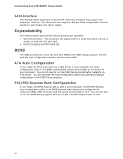
... Express add-in card in your computer. Intel Desktop Board D945GSEJT Product Guide SATA Interface The Desktop Board supports two Serial ATA channels (3.0 Gb/s) that add-in card. Expandability The Desktop Board provides the following expansion capability: • One... PCI connector. ATA Auto Configuration If you install a PCI/PCI Express add-in the BIOS Setup program. You can operate in card or a single- or dual-slot PCI riser card. • One PCI Express Full-Mini Card slot. BIOS The BIOS provides the Power...
... Express add-in card in your computer. Intel Desktop Board D945GSEJT Product Guide SATA Interface The Desktop Board supports two Serial ATA channels (3.0 Gb/s) that add-in card. Expandability The Desktop Board provides the following expansion capability: • One... PCI connector. ATA Auto Configuration If you install a PCI/PCI Express add-in the BIOS Setup program. You can operate in card or a single- or dual-slot PCI riser card. • One PCI Express Full-Mini Card slot. BIOS The BIOS provides the Power...
Product Guide
Page 22
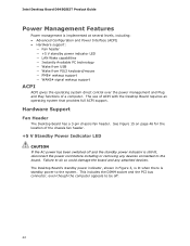
... though the computer appears to the system. Intel Desktop Board D945GSEJT Product Guide Power Management Features Power management is still lit, disconnect the power cord before installing or removing any attached devices. The Desktop Board's standby power indicator, shown in Figure 3, is lit when there is standby power to be off and the standby power indicator is implemented at several levels, including...
... though the computer appears to the system. Intel Desktop Board D945GSEJT Product Guide Power Management Features Power management is still lit, disconnect the power cord before installing or removing any attached devices. The Desktop Board's standby power indicator, shown in Figure 3, is lit when there is standby power to be off and the standby power indicator is implemented at several levels, including...

Product Guide
Page 23
Location of the Standby Power Indicator For more information on standby current requirements for the Desktop Board, refer to the Technical Product Specification on the Intel Desktop D945GSEJT web page at http://www.intel.com/products/motherboard/D945GSEJT/index.htm. 23 Desktop Board Features Figure 3.
Location of the Standby Power Indicator For more information on standby current requirements for the Desktop Board, refer to the Technical Product Specification on the Intel Desktop D945GSEJT web page at http://www.intel.com/products/motherboard/D945GSEJT/index.htm. 23 Desktop Board Features Figure 3.
Product Guide
Page 24
Intel Desktop Board D945GSEJT Product Guide Instantly Available PC Technology Instantly Available PC technology enables the board to its last known state. The board supports the PCI Bus Power Management Interface Specification. However, when the computer is in an ACPI S4 or S5 state, the only PS/2 activity that supports ...wake from USB requires the use of a USB peripheral that will blink). While in boards that powers up the computer. Add-in the ACPI S3 sleep-state, the computer will appear to be used to wake the computer. The LAN...
Intel Desktop Board D945GSEJT Product Guide Instantly Available PC Technology Instantly Available PC technology enables the board to its last known state. The board supports the PCI Bus Power Management Interface Specification. However, when the computer is in an ACPI S4 or S5 state, the only PS/2 activity that supports ...wake from USB requires the use of a USB peripheral that will blink). While in boards that powers up the computer. Add-in the ACPI S3 sleep-state, the computer will appear to be used to wake the computer. The LAN...
Product Guide
Page 27
... to: • Install the I/O shield • Install and remove the Desktop Board • Install and remove system memory • Connect SATA drives • Install a Wireless LAN card • Install an Intel Z-U130 USB Solid-State Drive (or compatible device) • Connect to ...equipment. Follow these guidelines before you can damage components. Some circuitry on the board can continue to disconnect power, telecommunications links, networks, or modems before you begin installing the Desktop Board: • Always follow the steps in each procedure in personal injury or ...
... to: • Install the I/O shield • Install and remove the Desktop Board • Install and remove system memory • Connect SATA drives • Install a Wireless LAN card • Install an Intel Z-U130 USB Solid-State Drive (or compatible device) • Connect to ...equipment. Follow these guidelines before you can damage components. Some circuitry on the board can continue to disconnect power, telecommunications links, networks, or modems before you begin installing the Desktop Board: • Always follow the steps in each procedure in personal injury or ...
Product Guide
Page 28
... in the installation instructions. Observe Safety and Regulatory Requirements Read and adhere to qualified technical personnel. Prevent Power Supply Overload Do not overload the power supply output. To avoid injury, be careful of: • Sharp pins on connectors or headers •... and cautions in this section and the instructions supplied with regional laws and regulations. Intel Desktop Board D945GSEJT Product Guide Installation Precautions When you install and test the Intel Desktop Board, observe all the modules within the computer is less than the output current rating ...
... in the installation instructions. Observe Safety and Regulatory Requirements Read and adhere to qualified technical personnel. Prevent Power Supply Overload Do not overload the power supply output. To avoid injury, be careful of: • Sharp pins on connectors or headers •... and cautions in this section and the instructions supplied with regional laws and regulations. Intel Desktop Board D945GSEJT Product Guide Installation Precautions When you install and test the Intel Desktop Board, observe all the modules within the computer is less than the output current rating ...

Product Guide
Page 30
... on installing and removing the Desktop Board. Disconnect the computer from its power source before you open the computer can result in personal injury or equipment damage. Refer to disconnect the power before performing the procedures described here. Intel Desktop Board D945GSEJT Mounting Screw Holes 30 Figure 5. Intel Desktop Board D945GSEJT Product Guide Installing and Removing the Desktop Board CAUTION Only qualified technical personnel...
... on installing and removing the Desktop Board. Disconnect the computer from its power source before you open the computer can result in personal injury or equipment damage. Refer to disconnect the power before performing the procedures described here. Intel Desktop Board D945GSEJT Mounting Screw Holes 30 Figure 5. Intel Desktop Board D945GSEJT Product Guide Installing and Removing the Desktop Board CAUTION Only qualified technical personnel...
Product Guide
Page 32
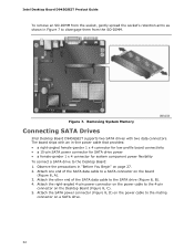
... 27. 2. Removing System Memory Connecting SATA Drives Intel Desktop Board D945GSEJT supports two SATA drives with an in-line power cable that provides: • a right-angled female-gender 1 x 4 connector for low-profile board connectivity • a 15-pin SATA power connector for SATA drive power • a female-gender 1 x 4 connector for system component power flexibility To connect a SATA drive to disengage...
... 27. 2. Removing System Memory Connecting SATA Drives Intel Desktop Board D945GSEJT supports two SATA drives with an in-line power cable that provides: • a right-angled female-gender 1 x 4 connector for low-profile board connectivity • a 15-pin SATA power connector for SATA drive power • a female-gender 1 x 4 connector for system component power flexibility To connect a SATA drive to disengage...

Product Guide
Page 33
Connecting the SATA Data and Power Cables 33 Installing and Replacing Desktop Board Components Figure 8.
Connecting the SATA Data and Power Cables 33 Installing and Replacing Desktop Board Components Figure 8.
Product Guide
Page 37
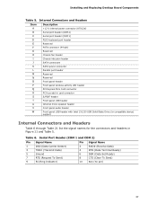
Installing and Replacing Desktop Board Components Table 5. Serial Port Header (COM 1 and COM 2) Pin ... 6. Internal Connectors and Headers Item A B C D E F G H I J K L M N O P Q R S T U V W Description +12 V internal power connector (ATX12V) Serial port header (COM 2) Serial port header (COM 1) PS/2 keyboard port header Reserved PATA connector (44-pin) Reserved Chassis fan header Chassis intrusion...USB header Internal mono speaker header Front panel audio header Front panel USB header with Intel Z-U130 USB Solid-State Drive (or compatible device) support Internal Connectors and Headers ...
Installing and Replacing Desktop Board Components Table 5. Serial Port Header (COM 1 and COM 2) Pin ... 6. Internal Connectors and Headers Item A B C D E F G H I J K L M N O P Q R S T U V W Description +12 V internal power connector (ATX12V) Serial port header (COM 2) Serial port header (COM 1) PS/2 keyboard port header Reserved PATA connector (44-pin) Reserved Chassis fan header Chassis intrusion...USB header Internal mono speaker header Front panel audio header Front panel USB header with Intel Z-U130 USB Solid-State Drive (or compatible device) support Internal Connectors and Headers ...
Product Guide
Page 39
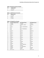
... ADDRSTB# PD3 GROUND PD4 GROUND PD5 GROUND PD6 GROUND PD7 GROUND INTR GROUND WAIT# GROUND PE GROUND SELECT KEY (no pin) 39 SATA Power Connector Pin Signal Name 1 +12 VDC 2 Ground 3 Ground 4 +5 VDC Table 12. Chassis Intrusion Header Pin Signal Name 1 Intruder# 2 Ground Table 11. Installing and Replacing Desktop Board Components Table 10.
... ADDRSTB# PD3 GROUND PD4 GROUND PD5 GROUND PD6 GROUND PD7 GROUND INTR GROUND WAIT# GROUND PE GROUND SELECT KEY (no pin) 39 SATA Power Connector Pin Signal Name 1 +12 VDC 2 Ground 3 Ground 4 +5 VDC Table 12. Chassis Intrusion Header Pin Signal Name 1 Intruder# 2 Ground Table 11. Installing and Replacing Desktop Board Components Table 10.


