
Product Guide
Page 5
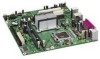
Contents 1 Desktop Board Features Desktop Board Components 10 Processor ...12 Main Memory...12 Intel® 945GC Express Chipset 13 S-Video Support 13 Onboard Audio Subsystem 13 Input/Output (I/O) Controller 14 LAN Subsystem 15 LAN Subsystem Software 15 LAN......18 Hardware Support 18 Power Connectors 18 Fan Headers 18 +5 V Standby Power Indicator LED 18 LAN Wake Capabilities 19 Wake from USB 19 Wake from PS/2 Keyboard/Mouse 20 PME# Wakeup Support 20 Battery ...20 Real-Time Clock 20 2 Installing and Replacing Desktop Board Components Before You Begin 21 Installation Precautions ...
Contents 1 Desktop Board Features Desktop Board Components 10 Processor ...12 Main Memory...12 Intel® 945GC Express Chipset 13 S-Video Support 13 Onboard Audio Subsystem 13 Input/Output (I/O) Controller 14 LAN Subsystem 15 LAN Subsystem Software 15 LAN......18 Hardware Support 18 Power Connectors 18 Fan Headers 18 +5 V Standby Power Indicator LED 18 LAN Wake Capabilities 19 Wake from USB 19 Wake from PS/2 Keyboard/Mouse 20 PME# Wakeup Support 20 Battery ...20 Real-Time Clock 20 2 Installing and Replacing Desktop Board Components Before You Begin 21 Installation Precautions ...

Product Guide
Page 6
Intel Desktop Board D945GCLF2 Product Guide Connecting to the Front Panel Header 32 Connecting the Hi-Speed USB 2.0 Headers 32 Connecting a Chassis Fan 33 Connecting Power Supply Cables 34 Setting the BIOS Configuration Jumper 35 Clearing Passwords 36 Replacing the Battery 37 3 Updating the BIOS Updating the BIOS with the Intel...Union Declaration of Conformity Statement 48 Product Ecology Statements 49 Recycling Considerations 49 Lead-free 2LI/Pb-free 2LI Board 52 Restriction of Hazardous Substances (RoHS 53 European Union RoHS 53 China RoHS 53 EMC Regulations 55 Ensure ...
Intel Desktop Board D945GCLF2 Product Guide Connecting to the Front Panel Header 32 Connecting the Hi-Speed USB 2.0 Headers 32 Connecting a Chassis Fan 33 Connecting Power Supply Cables 34 Setting the BIOS Configuration Jumper 35 Clearing Passwords 36 Replacing the Battery 37 3 Updating the BIOS Updating the BIOS with the Intel...Union Declaration of Conformity Statement 48 Product Ecology Statements 49 Recycling Considerations 49 Lead-free 2LI/Pb-free 2LI Board 52 Restriction of Hazardous Substances (RoHS 53 European Union RoHS 53 China RoHS 53 EMC Regulations 55 Ensure ...
Product Guide
Page 7
...Power LED Blink Codes 45 10. China RoHS Environmentally Friendly Use Period Mark 53 15. Location of the Chassis Fan Header 33 13. Intel Desktop Board D945GCLF2 Mounting Screw Holes 24 7. Installing the I/O Shield 23 6. Location of the Standby Power Indicator 19 5. ...Installing a DIMM 26 9. Front Panel Audio Header Signal Names for the BIOS Setup Program Modes 36 9. Intel Desktop Board D945GCLF2 Components 11 3. Removing the Battery 41 16. Lead-Free Second Level Interconnect Marks 52 14. Hi-Speed USB 2.0 Headers...
...Power LED Blink Codes 45 10. China RoHS Environmentally Friendly Use Period Mark 53 15. Location of the Chassis Fan Header 33 13. Intel Desktop Board D945GCLF2 Mounting Screw Holes 24 7. Installing the I/O Shield 23 6. Location of the Standby Power Indicator 19 5. ...Installing a DIMM 26 9. Front Panel Audio Header Signal Names for the BIOS Setup Program Modes 36 9. Intel Desktop Board D945GCLF2 Components 11 3. Removing the Battery 41 16. Lead-Free Second Level Interconnect Marks 52 14. Hi-Speed USB 2.0 Headers...
Product Guide
Page 18
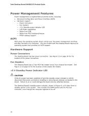
...could damage the board and any devices connected to the board. See Figure 13 on page 33 for the location of the chassis fan header. +5 V Standby Power Indicator LED CAUTION If the AC power has been switched off . 18 Intel Desktop Board D945GCLF2 Product Guide ...Power Management Features Power management is implemented at several levels, including: • Advanced Configuration and Power Interface (ACPI) • Hardware support: ― Power connectors ― Fan headers ― +5 V standby power indicator ...
...could damage the board and any devices connected to the board. See Figure 13 on page 33 for the location of the chassis fan header. +5 V Standby Power Indicator LED CAUTION If the AC power has been switched off . 18 Intel Desktop Board D945GCLF2 Product Guide ...Power Management Features Power management is implemented at several levels, including: • Advanced Configuration and Power Interface (ACPI) • Hardware support: ― Power connectors ― Fan headers ― +5 V standby power indicator ...

Product Guide
Page 21
...panel power button is not available, you can damage components. 2 Installing and Replacing Desktop Board Components This chapter tells you how to: • Install the I/O shield • Install and remove the Desktop Board • Install and remove memory • Connect the IDE cable • ...Connect the SATA cable • Connect internal headers • Connect chassis fan and power supply cables • Set the BIOS configuration and audio...
...panel power button is not available, you can damage components. 2 Installing and Replacing Desktop Board Components This chapter tells you how to: • Install the I/O shield • Install and remove the Desktop Board • Install and remove memory • Connect the IDE cable • ...Connect the SATA cable • Connect internal headers • Connect chassis fan and power supply cables • Set the BIOS configuration and audio...

Product Guide
Page 33
Location of the chassis fan header. Connect the chassis fan cable to this header. Figure 12. Installing and Replacing Desktop Board Components Connecting a Chassis Fan Figure 12 shows the location of the Chassis Fan Header 33
Location of the chassis fan header. Connect the chassis fan cable to this header. Figure 12. Installing and Replacing Desktop Board Components Connecting a Chassis Fan Figure 12 shows the location of the Chassis Fan Header 33


