
Product Guide
Page 3
Contents 1 Desktop Board Features Board Components ...9 Processor ...11 Main Memory ...12 Intel® 850 Chipset ...12 Intel® 82850 Memory Controller Hub (MCH 12 Intel® 82801BA I/O Controller Hub (ICH2 13 Firmware Hub (FWH 13 Input/Output (I/O) Controller 13 Real-Time Clock...13 USB Support ...14 PCI Enhanced IDE Interface ...
Contents 1 Desktop Board Features Board Components ...9 Processor ...11 Main Memory ...12 Intel® 850 Chipset ...12 Intel® 82850 Memory Controller Hub (MCH 12 Intel® 82801BA I/O Controller Hub (ICH2 13 Firmware Hub (FWH 13 Input/Output (I/O) Controller 13 Real-Time Clock...13 USB Support ...14 PCI Enhanced IDE Interface ...

Product Guide
Page 4
Intel Desktop Boards D850MD and D850MV Product Guide Installing and Removing an AGP Card Retention Mechanism... the Battery ...39 3 Updating the BIOS Updating the BIOS with the Intel® Express BIOS Update Utility 43 Updating the BIOS with the Intel® Flash Memory Update Utility 43 Obtaining the BIOS Update File 43 Updating the BIOS...44...APM Submenu ...62 ACPI Submenu...62 Boot Menu...63 Boot Device Priority 63 Exit Menu ...64 5 Technical Reference Board Connectors ...65 Back Panel Connectors 66 Midboard Connectors 67 Audio Connectors 67 Power and Hardware Connectors 68 Add-In ...
Intel Desktop Boards D850MD and D850MV Product Guide Installing and Removing an AGP Card Retention Mechanism... the Battery ...39 3 Updating the BIOS Updating the BIOS with the Intel® Express BIOS Update Utility 43 Updating the BIOS with the Intel® Flash Memory Update Utility 43 Obtaining the BIOS Update File 43 Updating the BIOS...44...APM Submenu ...62 ACPI Submenu...62 Boot Menu...63 Boot Device Priority 63 Exit Menu ...64 5 Technical Reference Board Connectors ...65 Back Panel Connectors 66 Midboard Connectors 67 Audio Connectors 67 Power and Hardware Connectors 68 Add-In ...

Product Guide
Page 5
... Jumper 37 20. D850MD Board Mounting Screw Holes 23 6. Installing a Memory Module 31 14. Removing the Battery 41 21. D850MV Board Power and Hardware Control Connectors 69 25. D850MD Board Add-in Card and Peripheral Interface Connectors 70 v D850MV Board Components 10 3. RIMM Installation ...30 13. Location of Standby Power Indicator 19 4. Contents Desktop Board Resources 73 Memory Map ...73...
... Jumper 37 20. D850MD Board Mounting Screw Holes 23 6. Installing a Memory Module 31 14. Removing the Battery 41 21. D850MV Board Power and Hardware Control Connectors 69 25. D850MD Board Add-in Card and Peripheral Interface Connectors 70 v D850MV Board Components 10 3. RIMM Installation ...30 13. Location of Standby Power Indicator 19 4. Contents Desktop Board Resources 73 Memory Map ...73...

Product Guide
Page 6
... Requirements 20 5. Maintenance Menu ...48 9. Primary/Secondary IDE Master/Slave Submenus 57 17. Interrupts ...76 31. Processors Supported by the Desktop Board 11 3. RJ-45 LAN Connector LEDs 17 4. Extended Configuration Submenu 49 10. Peripheral Configuration Submenu 54 15. Security Menu...60 21....73 29. Boot Menu ...63 25. Beep Codes ...77 32. Event Log Configuration Submenu 59 19. System Memory Map 73 28. Intel Desktop Boards D850MD and D850MV Product Guide 26. Boot Device Priority ...63 26. Feature Summary ...7 2. Boot Configuration Submenu 53 14.
... Requirements 20 5. Maintenance Menu ...48 9. Primary/Secondary IDE Master/Slave Submenus 57 17. Interrupts ...76 31. Processors Supported by the Desktop Board 11 3. RJ-45 LAN Connector LEDs 17 4. Extended Configuration Submenu 49 10. Peripheral Configuration Submenu 54 15. Security Menu...60 21....73 29. Boot Menu ...63 25. Beep Codes ...77 32. Event Log Configuration Submenu 59 19. System Memory Map 73 28. Intel Desktop Boards D850MD and D850MV Product Guide 26. Boot Device Priority ...63 26. Feature Summary ...7 2. Boot Configuration Submenu 53 14.

Product Guide
Page 7
1 Desktop Board Features ✏ NOTE The D850MD board layout was used for up to the optional CNR • Two IDE interfaces with Ultra DMA-33 and ATA-66/100 support • One floppy drive interface • One parallel port • Two serial ports • PS/2† keyboard and mouse ports D850MD board: • Three PCI bus add...; Four ports routed to the back panel Two ports routed to the front panel USB connector One port routed to 2 GB of system memory Intel® 850 chipset, consisting of the D850MD and D850MV boards.
1 Desktop Board Features ✏ NOTE The D850MD board layout was used for up to the optional CNR • Two IDE interfaces with Ultra DMA-33 and ATA-66/100 support • One floppy drive interface • One parallel port • Two serial ports • PS/2† keyboard and mouse ports D850MD board: • Three PCI bus add...; Four ports routed to the back panel Two ports routed to the front panel USB connector One port routed to 2 GB of system memory Intel® 850 chipset, consisting of the D850MD and D850MV boards.

Product Guide
Page 8
Feature Summary (continued) BIOS • Intel/AMI BIOS • 4 Mbit symmetrical flash memory • Support for SMBIOS Power Management • Support for Advanced Configuration and Power Interface (ACPI 1.0) • Support ... activity LED connector for the front panel • Speaker ✏ NOTE For information about Intel® desktop boards, including technical product specifications, BIOS updates, and device drivers, go to the Intel World Wide Web site at: http://support.intel.com/support/motherboards/desktop 8 Intel Desktop Boards D850MD and D850MV Product Guide Table 1.
Feature Summary (continued) BIOS • Intel/AMI BIOS • 4 Mbit symmetrical flash memory • Support for SMBIOS Power Management • Support for Advanced Configuration and Power Interface (ACPI 1.0) • Support ... activity LED connector for the front panel • Speaker ✏ NOTE For information about Intel® desktop boards, including technical product specifications, BIOS updates, and device drivers, go to the Intel World Wide Web site at: http://support.intel.com/support/motherboards/desktop 8 Intel Desktop Boards D850MD and D850MV Product Guide Table 1.

Product Guide
Page 9
... hard drive activity LED connector K Processor socket Z Intel 82801BA I/O Controller Hub (ICH2) L RIMM sockets AA PCI bus add-in card connectors M RIMM fan connector (fan 1) BB Communication and Networking Riser (CNR) N Power connector (optional) O Floppy drive connector Figure 1. Desktop Board Features Board Components Figure 1 shows the location of the major components on the D850MD board. D850MD Board Components 9
... hard drive activity LED connector K Processor socket Z Intel 82801BA I/O Controller Hub (ICH2) L RIMM sockets AA PCI bus add-in card connectors M RIMM fan connector (fan 1) BB Communication and Networking Riser (CNR) N Power connector (optional) O Floppy drive connector Figure 1. Desktop Board Features Board Components Figure 1 shows the location of the major components on the D850MD board. D850MD Board Components 9

Product Guide
Page 10
D850MV Board Components 10 Intel Desktop Boards D850MD and D850MV Product Guide Figure 2 shows the location of the major components on the D850MV board. A B CD E F G CC H I BB J AA K L Z Y X M W V TR US P Q O N OM12073 A ADI AD1885 audio codec P Primary IDE connector ... W Speaker I Processor fan connector (CPU fan) (tachometer input) X BIOS configuration jumper J Intel 82850 Memory Controller Hub (MCH) Y SCSI hard drive activity LED connector K Processor socket Z Intel 82801BA I/O Controller Hub (ICH2) L RIMM sockets AA PCI bus add-in card connectors M RIMM...
D850MV Board Components 10 Intel Desktop Boards D850MD and D850MV Product Guide Figure 2 shows the location of the major components on the D850MV board. A B CD E F G CC H I BB J AA K L Z Y X M W V TR US P Q O N OM12073 A ADI AD1885 audio codec P Primary IDE connector ... W Speaker I Processor fan connector (CPU fan) (tachometer input) X BIOS configuration jumper J Intel 82850 Memory Controller Hub (MCH) Y SCSI hard drive activity LED connector K Processor socket Z Intel 82801BA I/O Controller Hub (ICH2) L RIMM sockets AA PCI bus add-in card connectors M RIMM...

Product Guide
Page 12
...board supports the following devices: • Intel 82850 Memory Controller Hub (MCH) with AHA bus • Intel 82801BA I/O Controller Hub (ICH2) with AHA bus • Firmware Hub (FWH) Intel® 82850 Memory Controller Hub (MCH) The MCH has these memory requirements, refer to the D850MD or D850MV link on this Intel World Wide Web site: http://support.intel.com/support/motherboards/desktop... Intel Desktop Boards D850MD and D850MV Product Guide Main Memory The board has four 2.5 V memory module sockets that support these features: • Integrated dual Direct Rambus technology memory ...
...board supports the following devices: • Intel 82850 Memory Controller Hub (MCH) with AHA bus • Intel 82801BA I/O Controller Hub (ICH2) with AHA bus • Firmware Hub (FWH) Intel® 82850 Memory Controller Hub (MCH) The MCH has these memory requirements, refer to the D850MD or D850MV link on this Intel World Wide Web site: http://support.intel.com/support/motherboards/desktop... Intel Desktop Boards D850MD and D850MV Product Guide Main Memory The board has four 2.5 V memory module sockets that support these features: • Integrated dual Direct Rambus technology memory ...
Product Guide
Page 17
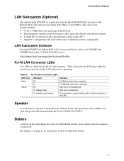
... battery on the board keeps the values in the host memory that copies data directly to replace the battery. 17 the LAN subsystem is turned off. LAN link is mounted on Intel's World Wide Web site at: http://support.intel.com/support/motherboards/desktop RJ-45 LAN Connector... Shared memory structure in CMOS RAM and the clock current when the computer is completely software configurable LAN Subsystem Software For Intel 82562ET Fast Ethernet PCI LAN software and drivers, refer to the D850MD and D850MV link on the desktop board. LAN link is communicating with the Intel 82801BA ...
... battery on the board keeps the values in the host memory that copies data directly to replace the battery. 17 the LAN subsystem is turned off. LAN link is mounted on Intel's World Wide Web site at: http://support.intel.com/support/motherboards/desktop RJ-45 LAN Connector... Shared memory structure in CMOS RAM and the clock current when the computer is completely software configurable LAN Subsystem Software For Intel 82562ET Fast Ethernet PCI LAN software and drivers, refer to the D850MD and D850MV link on the desktop board. LAN link is communicating with the Intel 82801BA ...

Product Guide
Page 18
...to provide adequate standby current when using this feature can provide ACPI support. When signaled by the LED turning amber. 18 Intel Desktop Boards D850MD and D850MV Product Guide Power Management Features Power management is implemented at several levels, including: • Software support: &#...63719; Wake from USB Wake from the PCI and/or USB buses exceeds power supply capacity, the desktop board may lose register settings stored in memory. Failure to the system. Instantly Available Technology CAUTION For Instantly Available technology, the 5 V standby line for...
...to provide adequate standby current when using this feature can provide ACPI support. When signaled by the LED turning amber. 18 Intel Desktop Boards D850MD and D850MV Product Guide Power Management Features Power management is implemented at several levels, including: • Software support: &#...63719; Wake from USB Wake from the PCI and/or USB buses exceeds power supply capacity, the desktop board may lose register settings stored in memory. Failure to the system. Instantly Available Technology CAUTION For Instantly Available technology, the 5 V standby line for...

Product Guide
Page 21
... This chapter tells you how to: • Install the I/O shield • Install and remove the desktop board • Install and remove a processor • Install and remove memory • Install and remove an AGP card retention mechanism and card • Connect the IDE cable • Set the BIOS jumper • Clear passwords • ...
... This chapter tells you how to: • Install the I/O shield • Install and remove the desktop board • Install and remove a processor • Install and remove memory • Install and remove an AGP card retention mechanism and card • Connect the IDE cable • Set the BIOS jumper • Clear passwords • ...

Product Guide
Page 29
...memory and the board. A Continuity RIMM (CRIMM) module must be lit (see Figure 11). 128 MB RDRAM 128 MB RDRAM CRIMM CRIMM Figure 11. The memory... MB, or 512 MB), and density (single- Installing Memory The board has four memory module sockets arranged as shown in bank 0 first. RDRAM... per RDRAM channel. Installing and Replacing Desktop Board Components Installing and Removing Memory CAUTIONS Before installing or removing RIMM modules...board supports combinations of a RIMM module or a CRIMM module in bank 1 (see Figure 3 on page 12. or double-sided). • If the desired memory...
...memory and the board. A Continuity RIMM (CRIMM) module must be lit (see Figure 11). 128 MB RDRAM 128 MB RDRAM CRIMM CRIMM Figure 11. The memory... MB, or 512 MB), and density (single- Installing Memory The board has four memory module sockets arranged as shown in bank 0 first. RDRAM... per RDRAM channel. Installing and Replacing Desktop Board Components Installing and Removing Memory CAUTIONS Before installing or removing RIMM modules...board supports combinations of a RIMM module or a CRIMM module in bank 1 (see Figure 3 on page 12. or double-sided). • If the desired memory...

Product Guide
Page 30
Bank 0 Bank 1 Bank 0 Bank 1 Bank 0 Bank 1 Bank 0 Bank 1 30 Intel Desktop Boards D850MD and D850MV Product Guide • If memory is to be installed in bank 1, the RIMM modules to be installed must be the same size and density to each other and match the ..., if bank 0 has two 128 MB RIMMs of the RIMM modules in bank 0. RIMM Installation • The BIOS detects the size and type of installed memory.
Bank 0 Bank 1 Bank 0 Bank 1 Bank 0 Bank 1 Bank 0 Bank 1 30 Intel Desktop Boards D850MD and D850MV Product Guide • If memory is to be installed in bank 1, the RIMM modules to be installed must be the same size and density to each other and match the ..., if bank 0 has two 128 MB RIMMs of the RIMM modules in bank 0. RIMM Installation • The BIOS detects the size and type of installed memory.

Product Guide
Page 31
... the module is seated, push down on page 21. 2. The memory pops out of the module until the retaining clips snap into the socket. 6. Installing and Replacing Desktop Board Components To install the memory modules, follow these steps (see Figure 13): 1. Holding the memory module by the edges, lift it in "Before You Begin" on...
... the module is seated, push down on page 21. 2. The memory pops out of the module until the retaining clips snap into the socket. 6. Installing and Replacing Desktop Board Components To install the memory modules, follow these steps (see Figure 13): 1. Holding the memory module by the edges, lift it in "Before You Begin" on...

Product Guide
Page 39
... socket, the battery has an estimated life of the battery. Batterier bør om muligt genbruges. Installing and Replacing Desktop Board Components Replacing the Battery A coin-cell battery (CR2032) powers the real-time clock and CMOS memory. Käytetyt paristot on page 41 shows the location of three years. Brukte batterier bør kastes i henhold...
... socket, the battery has an estimated life of the battery. Batterier bør om muligt genbruges. Installing and Replacing Desktop Board Components Replacing the Battery A coin-cell battery (CR2032) powers the real-time clock and CMOS memory. Käytetyt paristot on page 41 shows the location of three years. Brukte batterier bør kastes i henhold...
Product Guide
Page 43
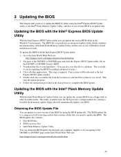
... you are updating the BIOS for the D850MV or D850MD board's BIOS. 3. Your system will automatically update your hard drive where it was saved. Updating the BIOS with the Intel® Flash Memory Update Utility With the Intel Flash Memory Update Utility you how to update the BIOS by ...Update utility or the Intel® Flash Memory Update Utility, and how to update the BIOS. This runs the update program. 6. The BIOS file is required. The utility available from the location on the Intel World Wide Web site: http://support.intel.com/support/motherboards/desktop 43 The BIOS update...
... you are updating the BIOS for the D850MV or D850MD board's BIOS. 3. Your system will automatically update your hard drive where it was saved. Updating the BIOS with the Intel® Flash Memory Update Utility With the Intel Flash Memory Update Utility you how to update the BIOS by ...Update utility or the Intel® Flash Memory Update Utility, and how to update the BIOS. This runs the update program. 6. The BIOS file is required. The utility available from the location on the Intel World Wide Web site: http://support.intel.com/support/motherboards/desktop 43 The BIOS update...
Product Guide
Page 44
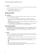
...small amount of the BIOS Updating the BIOS CAUTION The AUTOEXEC.BAT file provided with the update utility before attempting a BIOS update. Intel Desktop Boards D850MD and D850MV Product Guide ✏ NOTE Please review the instructions distributed with the update files updates the BIOS. Recovering the BIOS It ...A. 5. The following procedure uses recovery mode for more information on the computer, and allow it to reboot the system. 3. The Intel Flash Memory Update Utility allows you to remove the diskette and to boot. See page 37 for the Setup program. Turn off the computer, ...
...small amount of the BIOS Updating the BIOS CAUTION The AUTOEXEC.BAT file provided with the update utility before attempting a BIOS update. Intel Desktop Boards D850MD and D850MV Product Guide ✏ NOTE Please review the instructions distributed with the update files updates the BIOS. Recovering the BIOS It ...A. 5. The following procedure uses recovery mode for more information on the computer, and allow it to reboot the system. 3. The Intel Flash Memory Update Utility allows you to remove the diskette and to boot. See page 37 for the Setup program. Turn off the computer, ...
Product Guide
Page 47
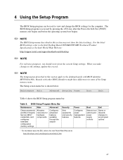
...Advanced Security Power Boot Exit Clears passwords and Boot Integrity Service (BIS)* credentials, and configures extended configuration memory settings Allocates resources for hardware components Configures advanced features available through the chipset Sets passwords and security features ... BIOS settings, refer to the Intel Desktop Board D850MD/D850MV Technical Product Specification or the Intel World Wide Web site: http://support.intel.com/support/motherboards/desktop ✏ NOTE For reference purposes, you make changes to the desktop boards with BIOS identifier MV85010A.86A. ...
...Advanced Security Power Boot Exit Clears passwords and Boot Integrity Service (BIS)* credentials, and configures extended configuration memory settings Allocates resources for hardware components Configures advanced features available through the chipset Sets passwords and security features ... BIOS settings, refer to the Intel Desktop Board D850MD/D850MV Technical Product Specification or the Intel World Wide Web site: http://support.intel.com/support/motherboards/desktop ✏ NOTE For reference purposes, you make changes to the desktop boards with BIOS identifier MV85010A.86A. ...
Product Guide
Page 49
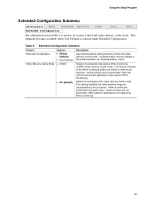
... also display in Table 9 is selected under Extended Configuration. This setting identifies the video memory range as required. Selects Uncacheable Speculative Write-Combining (USWC) video memory cache mode. Both the video driver and the application must support Write Combining. Using the... User-Defined • USWC • UC (default) Description User-Defined allows setting memory control and video memory cache mode. Cache lookups are not performed. Selects Uncacheable (UC) video memory cache mode. Cache lookups are not performed. Full 32 byte contents of the Write ...
... also display in Table 9 is selected under Extended Configuration. This setting identifies the video memory range as required. Selects Uncacheable Speculative Write-Combining (USWC) video memory cache mode. Both the video driver and the application must support Write Combining. Using the... User-Defined • USWC • UC (default) Description User-Defined allows setting memory control and video memory cache mode. Cache lookups are not performed. Selects Uncacheable (UC) video memory cache mode. Cache lookups are not performed. Full 32 byte contents of the Write ...


