

Product Guide
Page 4
... 34 Removing the AGP Card Retention Mechanism 35 Connecting the IDE Cable 36 Setting the BIOS Configuration Jumper 37 Clearing Passwords...38 Replacing the Battery ...39 3 Updating the BIOS Updating the BIOS with the Intel® Express BIOS Update Utility 43 Updating the BIOS with the Intel® Flash Memory Update Utility 43 Obtaining the BIOS Update File 43 Updating the BIOS...44 Recovering the BIOS 44 4 Using the Setup Program Maintenance Menu...48 Extended Configuration Submenu 49 Main Menu ...50 Advanced Menu ...51 PCI Configuration Submenu 52 Boot Configuration Submenu...
... 34 Removing the AGP Card Retention Mechanism 35 Connecting the IDE Cable 36 Setting the BIOS Configuration Jumper 37 Clearing Passwords...38 Replacing the Battery ...39 3 Updating the BIOS Updating the BIOS with the Intel® Express BIOS Update Utility 43 Updating the BIOS with the Intel® Flash Memory Update Utility 43 Obtaining the BIOS Update File 43 Updating the BIOS...44 Recovering the BIOS 44 4 Using the Setup Program Maintenance Menu...48 Extended Configuration Submenu 49 Main Menu ...50 Advanced Menu ...51 PCI Configuration Submenu 52 Boot Configuration Submenu...

Product Guide
Page 6
... 20. Power Menu...61 22. Standby Current Requirements 20 5. Advanced Menu ...51 12. Event Log Configuration Submenu 59 19. I/O Map...74 30. BIOS Setup Program Function Keys 48 8. Peripheral Configuration Submenu 54 15. DMA Channels...73 29. Main Menu ...50 11. ACPI Submenu ...62 24. Interrupts ...76 31. Boot Device Priority ...63 26. Beep Codes ...77 32. Intel Desktop Boards D850MD and D850MV Product Guide 26. PCI Configuration Submenu 52 13. System Memory Map...
... 20. Power Menu...61 22. Standby Current Requirements 20 5. Advanced Menu ...51 12. Event Log Configuration Submenu 59 19. I/O Map...74 30. BIOS Setup Program Function Keys 48 8. Peripheral Configuration Submenu 54 15. DMA Channels...73 29. Main Menu ...50 11. ACPI Submenu ...62 24. Interrupts ...76 31. Boot Device Priority ...63 26. Beep Codes ...77 32. Intel Desktop Boards D850MD and D850MV Product Guide 26. PCI Configuration Submenu 52 13. System Memory Map...

Product Guide
Page 8
... temperature sensing • Voltage sensing to detect out of range values Instantly Available PC • Support for PCI Local Bus Specification Revision 2.2 • Suspend to RAM (STR) support • Wake on USB, PCI, CNR, RS-232, PS/2, LAN, and front panel Other Features • SCSI hard drive activity LED connector for the front panel • Speaker ✏ NOTE For information about Intel® desktop boards, including technical product specifications, BIOS updates, and device drivers, go to the Intel...
... temperature sensing • Voltage sensing to detect out of range values Instantly Available PC • Support for PCI Local Bus Specification Revision 2.2 • Suspend to RAM (STR) support • Wake on USB, PCI, CNR, RS-232, PS/2, LAN, and front panel Other Features • SCSI hard drive activity LED connector for the front panel • Speaker ✏ NOTE For information about Intel® desktop boards, including technical product specifications, BIOS updates, and device drivers, go to the Intel...

Product Guide
Page 9
... connector U Chassis fan connector (fan 2) (tachometer input) G Back panel connectors V Battery H ATX12V processor core voltage connector W Speaker I Processor fan connector (CPU fan) (tachometer input) X BIOS configuration jumper J Intel 82850 Memory Controller Hub (MCH) Y SCSI hard drive activity LED connector K Processor socket Z Intel 82801BA I/O Controller Hub (ICH2) L RIMM sockets AA PCI bus add-in card connectors M RIMM fan connector (fan 1) BB Communication and Networking Riser (CNR) N Power connector (optional) O Floppy drive connector Figure 1. D850MD Board...
... connector U Chassis fan connector (fan 2) (tachometer input) G Back panel connectors V Battery H ATX12V processor core voltage connector W Speaker I Processor fan connector (CPU fan) (tachometer input) X BIOS configuration jumper J Intel 82850 Memory Controller Hub (MCH) Y SCSI hard drive activity LED connector K Processor socket Z Intel 82801BA I/O Controller Hub (ICH2) L RIMM sockets AA PCI bus add-in card connectors M RIMM fan connector (fan 1) BB Communication and Networking Riser (CNR) N Power connector (optional) O Floppy drive connector Figure 1. D850MD Board...

Product Guide
Page 10
... panel USB connector D CD-ROM connector (ATAPI) S Alternate power/sleep LED connector E Front panel audio connector T Front panel connector F Chassis intrusion connector U Chassis fan connector (fan 2) (tachometer input) G Back panel connectors V Battery H ATX12V processor core voltage connector W Speaker I Processor fan connector (CPU fan) (tachometer input) X BIOS configuration jumper J Intel 82850 Memory Controller Hub (MCH) Y SCSI hard drive activity LED connector K Processor socket Z Intel 82801BA I/O Controller Hub (ICH2) L RIMM sockets AA PCI bus add-in card connectors...
... panel USB connector D CD-ROM connector (ATAPI) S Alternate power/sleep LED connector E Front panel audio connector T Front panel connector F Chassis intrusion connector U Chassis fan connector (fan 2) (tachometer input) G Back panel connectors V Battery H ATX12V processor core voltage connector W Speaker I Processor fan connector (CPU fan) (tachometer input) X BIOS configuration jumper J Intel 82850 Memory Controller Hub (MCH) Y SCSI hard drive activity LED connector K Processor socket Z Intel 82801BA I/O Controller Hub (ICH2) L RIMM sockets AA PCI bus add-in card connectors...
Product Guide
Page 11
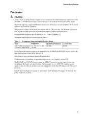
... power connector locations. 11 Processors Supported by the Desktop Board Type Designation System Bus Frequency Intel Pentium 4 processor 1.4, 1.5, 1.6, 1.7, and 400 MHz in damage to install a processor, see Chapter 2 on how to the desktop board and/or power supply. Processors are needed to provide extra power to the Intel 850 chipset and Pentium 4 processor. For instructions on page 21. The board supports a single Intel Pentium 4 processor. Desktop Board Features Processor CAUTION Failure to use an ATX12V power supply, or not connecting the additional power supply lead...
... power connector locations. 11 Processors Supported by the Desktop Board Type Designation System Bus Frequency Intel Pentium 4 processor 1.4, 1.5, 1.6, 1.7, and 400 MHz in damage to install a processor, see Chapter 2 on how to the desktop board and/or power supply. Processors are needed to provide extra power to the Intel 850 chipset and Pentium 4 processor. For instructions on page 21. The board supports a single Intel Pentium 4 processor. Desktop Board Features Processor CAUTION Failure to use an ATX12V power supply, or not connecting the additional power supply lead...

Product Guide
Page 12
...; Firmware Hub (FWH) Intel® 82850 Memory Controller Hub (MCH) The MCH has these memory requirements, refer to 2 GB main system memory • Auto-detection of 32 RDRAM devices per channel • 128 MB (minimum) to 2 GB (maximum) onboard capacity utilizing 128/144 Mbit or 256/288 Mbit technology • Single- Intel Desktop Boards D850MD and D850MV Product Guide Main Memory The board has four 2.5 V memory module sockets that support these features: • Integrated dual...
...; Firmware Hub (FWH) Intel® 82850 Memory Controller Hub (MCH) The MCH has these memory requirements, refer to 2 GB main system memory • Auto-detection of 32 RDRAM devices per channel • 128 MB (minimum) to 2 GB (maximum) onboard capacity utilizing 128/144 Mbit or 256/288 Mbit technology • Single- Intel Desktop Boards D850MD and D850MV Product Guide Main Memory The board has four 2.5 V memory module sockets that support these features: • Integrated dual...

Product Guide
Page 15
...: http://support.intel.com/support/motherboards/desktop BIOS The BIOS provides the Power-On Self-Test (POST), the BIOS Setup program, the PCI and IDE auto-configuration utilities, and the video BIOS. An AGP card retention mechanism (RM) may occur if passive (non-amplified) speakers are connected to be updated by following : • Intel 82801BA I /O space) for that supports various features such as 3D graphics. PCI Auto Configuration If you install a PCI add-in the Firmware Hub. Communication and Networking Riser (CNR) (Optional...
...: http://support.intel.com/support/motherboards/desktop BIOS The BIOS provides the Power-On Self-Test (POST), the BIOS Setup program, the PCI and IDE auto-configuration utilities, and the video BIOS. An AGP card retention mechanism (RM) may occur if passive (non-amplified) speakers are connected to be updated by following : • Intel 82801BA I /O space) for that supports various features such as 3D graphics. PCI Auto Configuration If you install a PCI add-in the Firmware Hub. Communication and Networking Riser (CNR) (Optional...

Product Guide
Page 16
... only the supervisor password is booted. Setup options are set , you install an IDE device (such as a hard drive) in your computer, the IDE auto-configuration utility in the BIOS Setup program. The password prompt is displayed before the computer is set , pressing at the password prompt of Setup gives the user restricted access to Setup. • If both passwords are then available for a password. Intel Desktop Boards D850MD and D850MV Product Guide IDE Auto Configuration If you must enter either password to boot the computer. 16...
... only the supervisor password is booted. Setup options are set , you install an IDE device (such as a hard drive) in your computer, the IDE auto-configuration utility in the BIOS Setup program. The password prompt is displayed before the computer is set , pressing at the password prompt of Setup gives the user restricted access to Setup. • If both passwords are then available for a password. Intel Desktop Boards D850MD and D850MV Product Guide IDE Auto Configuration If you must enter either password to boot the computer. 16...

Product Guide
Page 18
... Available technology enables the board to enter the ACPI S3 (Suspend-to-RAM) sleep state. Intel Desktop Boards D850MD and D850MV Product Guide Power Management Features Power management is implemented at several levels, including: • Software support: Advanced Configuration and Power Interface (ACPI) Advanced Power Management (APM) • Hardware support: Instantly Available technology Resume on Ring Wake from USB Wake from the PCI and/or USB buses exceeds power supply capacity, the desktop board may...
... Available technology enables the board to enter the ACPI S3 (Suspend-to-RAM) sleep state. Intel Desktop Boards D850MD and D850MV Product Guide Power Management Features Power management is implemented at several levels, including: • Software support: Advanced Configuration and Power Interface (ACPI) Advanced Power Management (APM) • Hardware support: Instantly Available technology Resume on Ring Wake from USB Wake from the PCI and/or USB buses exceeds power supply capacity, the desktop board may...

Product Guide
Page 37
... modes. The BIOS attempts to clear passwords. A recovery diskette is shown in unreliable computer operation. The location of the BIOS Configuration Jumper The three-pin BIOS jumper enables the board configuration to be done in BIOS Setup. Table 5 shows the jumper settings for booting. After the POST runs, the BIOS displays the maintenance menu. Moving the jumper with the power on may result in Figure 19. 1 3 J9H2 OM11836 Figure 19. Use this menu to recover the BIOS configuration. Installing and Replacing Desktop Board Components Setting...
... modes. The BIOS attempts to clear passwords. A recovery diskette is shown in unreliable computer operation. The location of the BIOS Configuration Jumper The three-pin BIOS jumper enables the board configuration to be done in BIOS Setup. Table 5 shows the jumper settings for booting. After the POST runs, the BIOS displays the maintenance menu. Moving the jumper with the power on may result in Figure 19. 1 3 J9H2 OM11836 Figure 19. Use this menu to recover the BIOS configuration. Installing and Replacing Desktop Board Components Setting...
Product Guide
Page 47
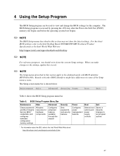
...://support.intel.com/support/motherboards/desktop ✏ NOTE For reference purposes, you make changes to the settings, update this record. ✏ NOTE The Setup menus described in some of the Setup menu screens. Boards with BIOS identifier MV85010A.86A. 4 Using the Setup Program The BIOS Setup program can be used to view and change the BIOS settings for hardware components Configures advanced features available through the chipset Sets passwords and security features Configures power management features Selects boot options and power supply controls...
...://support.intel.com/support/motherboards/desktop ✏ NOTE For reference purposes, you make changes to the settings, update this record. ✏ NOTE The Setup menus described in some of the Setup menu screens. Boards with BIOS identifier MV85010A.86A. 4 Using the Setup Program The BIOS Setup program can be used to view and change the BIOS settings for hardware components Configures advanced features available through the chipset Sets passwords and security features Configures power management features Selects boot options and power supply controls...
Product Guide
Page 49
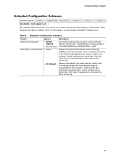
... support Write Combining. If selected here, will also display in the Advanced Menu as uncacheable by the processor. Selects Uncacheable Speculative Write-Combining (USWC) video memory cache mode. Extended Configuration Submenu Feature Extended Configuration Video Memory Cache Mode Options • Default (default) • User-Defined • USWC • UC (default) Description User-Defined allows setting memory control and video memory cache mode. Using the Setup Program Extended Configuration Submenu Maintenance Main Advanced Security Extended Configuration Power Boot...
... support Write Combining. If selected here, will also display in the Advanced Menu as uncacheable by the processor. Selects Uncacheable Speculative Write-Combining (USWC) video memory cache mode. Extended Configuration Submenu Feature Extended Configuration Video Memory Cache Mode Options • Default (default) • User-Defined • USWC • UC (default) Description User-Defined allows setting memory control and video memory cache mode. Using the Setup Program Extended Configuration Submenu Maintenance Main Advanced Security Extended Configuration Power Boot...
Product Guide
Page 55
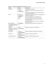
... displayed • IRQ 7 (default) only if Parallel Port is Enhanced Capabilities Port mode, a high-speed bi-directional mode. Enables or disables the onboard audio subsystem. Using the Setup Program Table 14. Peripheral Configuration Submenu (continued) Feature Parallel port Mode Options • Disabled • Enabled • Auto (default) • Output Only • Bi-directional (default) • EPP • ECP Base I /O address for the parallel port. Enables or disables USB legacy support. 55 Not available if the parallel port is Extended Parallel Port mode, a high...
... displayed • IRQ 7 (default) only if Parallel Port is Enhanced Capabilities Port mode, a high-speed bi-directional mode. Enables or disables the onboard audio subsystem. Using the Setup Program Table 14. Peripheral Configuration Submenu (continued) Feature Parallel port Mode Options • Disabled • Enabled • Auto (default) • Output Only • Bi-directional (default) • EPP • ECP Base I /O address for the parallel port. Enables or disables USB legacy support. 55 Not available if the parallel port is Extended Parallel Port mode, a high...

Product Guide
Page 56
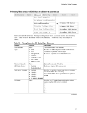
... Specifies the integrated IDE controller. Specifies the hard disk drive pre-delay. Reports type of connected IDE device. Intel Desktop Boards D850MD and D850MV Product Guide IDE Configuration Submenu Maintenance Main Advanced Security Power PCI Configuration Boot Configuration Peripheral Configuration IDE Configuration Diskette Configuration Event Log Configuration Video Configuration Boot This submenu shown in Table 15 is used to configure IDE device options. When selected, displays the Secondary IDE Master submenu. Reports type of connected IDE device. Exit Table 15...
... Specifies the integrated IDE controller. Specifies the hard disk drive pre-delay. Reports type of connected IDE device. Intel Desktop Boards D850MD and D850MV Product Guide IDE Configuration Submenu Maintenance Main Advanced Security Power PCI Configuration Boot Configuration Peripheral Configuration IDE Configuration Diskette Configuration Event Log Configuration Video Configuration Boot This submenu shown in Table 15 is used to configure IDE device options. When selected, displays the Secondary IDE Master submenu. Reports type of connected IDE device. Exit Table 15...
Product Guide
Page 57
... be changed. • Auto (default) Auto fills-in capabilities from ATA/ATAPI device. • CD-ROM • ATAPI Removable • Other ATAPI • IDE Removable None Displays the capacity of the drive. • Disabled Enables or disables LBA mode control. • Enabled (default) • Disabled • 2 Sectors • 4 Sectors • 8 Sectors Specifies the number of these configuration options appear only if an IDE device is shown. Check the hard disk drive's specifications for IDE devices. • User User allows capabilities to memory...
... be changed. • Auto (default) Auto fills-in capabilities from ATA/ATAPI device. • CD-ROM • ATAPI Removable • Other ATAPI • IDE Removable None Displays the capacity of the drive. • Disabled Enables or disables LBA mode control. • Enabled (default) • Disabled • 2 Sectors • 4 Sectors • 8 Sectors Specifies the number of these configuration options appear only if an IDE device is shown. Check the hard disk drive's specifications for IDE devices. • User User allows capabilities to memory...
Product Guide
Page 58
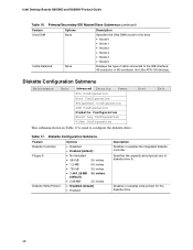
... the integrated diskette controller. Boot Exit Table 17. Disables or enables write-protect for the drive. • Mode 0 • Mode 1 • Mode 2 • Mode 3 • Mode 4 • Mode 5 Displays the type of diskette drive A. Intel Desktop Boards D850MD and D850MV Product Guide Table 16. Diskette Configuration Submenu Maintenance Main Advanced Security Power PCI Configuration Boot Configuration Peripheral Configuration IDE Configuration Diskette Configuration Event Log Configuration Video Configuration This submenu shown in Table 17 is used to the IDE interface: 40...
... the integrated diskette controller. Boot Exit Table 17. Disables or enables write-protect for the drive. • Mode 0 • Mode 1 • Mode 2 • Mode 3 • Mode 4 • Mode 5 Displays the type of diskette drive A. Intel Desktop Boards D850MD and D850MV Product Guide Table 16. Diskette Configuration Submenu Maintenance Main Advanced Security Power PCI Configuration Boot Configuration Peripheral Configuration IDE Configuration Diskette Configuration Event Log Configuration Video Configuration This submenu shown in Table 17 is used to the IDE interface: 40...

Product Guide
Page 60
... the supervisor password. Enabled allows system to set . Intel Desktop Boards D850MD and D850MV Product Guide Security Menu Maintenance Main Advanced Security Power Boot The menu shown in Table 20 is used to complete the boot process without a password. Sets BIOS Setup Utility access rights for user level. Security Menu If no password was entered previously: Feature Options Description Supervisor Password Is User Password Is Set Supervisor Password Set User Password Clear User Password (Note 1) User Access Level (Note 2) Unattended Start (Note 1) No options No options Password can...
... the supervisor password. Enabled allows system to set . Intel Desktop Boards D850MD and D850MV Product Guide Security Menu Maintenance Main Advanced Security Power Boot The menu shown in Table 20 is used to complete the boot process without a password. Sets BIOS Setup Utility access rights for user level. Security Menu If no password was entered previously: Feature Options Description Supervisor Password Is User Password Is Set Supervisor Password Set User Password Clear User Password (Note 1) User Access Level (Note 2) Unattended Start (Note 1) No options No options Password can...
Product Guide
Page 63
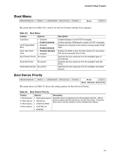
... BIOS Boot Scan User Flash Area Boot Device Priority Options • Disabled • Enabled (default) • Disabled • Enabled (default) • Disabled (default) • Enabled No options Hard Disk Drives No options Removable Devices No options Description Disabled displays normal POST messages. Boot Device Priority Maintenance Main Advanced Security Power Boot Exit Boot Device Priority The menu shown in Table 24 is used to set the selection as the intended boot device. • ATAPI CD-ROM • Intel® Boot A • Disabled 63 Using the Setup...
... BIOS Boot Scan User Flash Area Boot Device Priority Options • Disabled • Enabled (default) • Disabled • Enabled (default) • Disabled (default) • Enabled No options Hard Disk Drives No options Removable Devices No options Description Disabled displays normal POST messages. Boot Device Priority Maintenance Main Advanced Security Power Boot Exit Boot Device Priority The menu shown in Table 24 is used to set the selection as the intended boot device. • ATAPI CD-ROM • Intel® Boot A • Disabled 63 Using the Setup...

Product Guide
Page 78
... has been stored in CMOS. CMOS Date/Time Not Set The time and/or date values stored in the keyboard connection. Run Setup to access diskette drive controller. Checking NVRAM..... Keyboard Error Error in CMOS are not the same as the last boot. Intel Desktop Boards D850MD and D850MV Product Guide BIOS Error Messages When a recoverable error occurs during read sector from diskette drive. ATAPI Incompatible Sec Master Drive - CMOS Display Type Wrong The display type is incorrect. NVRAM...
... has been stored in CMOS. CMOS Date/Time Not Set The time and/or date values stored in the keyboard connection. Run Setup to access diskette drive controller. Checking NVRAM..... Keyboard Error Error in CMOS are not the same as the last boot. Intel Desktop Boards D850MD and D850MV Product Guide BIOS Error Messages When a recoverable error occurs during read sector from diskette drive. ATAPI Incompatible Sec Master Drive - CMOS Display Type Wrong The display type is incorrect. NVRAM...


