Product Guide
Page 5
Contents 1 Desktop Board Features Desktop Board Components 11 Processor ...13 Main Memory ...14 Intel® 845GV Chipset ...15 Audio Subsystem ...15 LAN Subsystem (Optional 16 LAN Subsystem Software 16 RJ-45 LAN Connector LEDs 16 Hi-Speed...22 Installing the I/O Shield ...24 Installing and Removing the Desktop Board 25 Installing and Removing a Processor 26 Installing a Processor 26 Installing the Processor Fan Heatsink 26 Connecting the Processor Fan Heatsink Cable 27 Removing a Processor 27 Installing and Removing Memory 28 Installing DIMMs ...28 Removing DIMMs ...29 Connecting the ...
Contents 1 Desktop Board Features Desktop Board Components 11 Processor ...13 Main Memory ...14 Intel® 845GV Chipset ...15 Audio Subsystem ...15 LAN Subsystem (Optional 16 LAN Subsystem Software 16 RJ-45 LAN Connector LEDs 16 Hi-Speed...22 Installing the I/O Shield ...24 Installing and Removing the Desktop Board 25 Installing and Removing a Processor 26 Installing a Processor 26 Installing the Processor Fan Heatsink 26 Connecting the Processor Fan Heatsink Cable 27 Removing a Processor 27 Installing and Removing Memory 28 Installing DIMMs ...28 Removing DIMMs ...29 Connecting the ...
Product Guide
Page 6
Intel Desktop Board D845GVSR Product Guide Connecting Add-In Card and Peripheral Interface Connectors 36 Setting the BIOS Configuration Jumper Block 37 Clearing Passwords ...38 Back Panel Connectors ...39 Replacing the Battery ...40 3 Updating the BIOS Updating the BIOS with the Intel® Express BIOS Update Utility 45 Updating the BIOS with the Intel... Drives Submenu 71 Removable Devices Submenu 72 ATAPI CD-ROM Drives 73 Exit Menu ...74 5 Desktop Board Resources Memory Map ...75 DMA Channels ...75 Interrupts ...76 A Error Messages and Indicators BIOS Beep Codes ...77 BIOS Error Messages ...
Intel Desktop Board D845GVSR Product Guide Connecting Add-In Card and Peripheral Interface Connectors 36 Setting the BIOS Configuration Jumper Block 37 Clearing Passwords ...38 Back Panel Connectors ...39 Replacing the Battery ...40 3 Updating the BIOS Updating the BIOS with the Intel® Express BIOS Update Utility 45 Updating the BIOS with the Intel... Drives Submenu 71 Removable Devices Submenu 72 ATAPI CD-ROM Drives 73 Exit Menu ...74 5 Desktop Board Resources Memory Map ...75 DMA Channels ...75 Interrupts ...76 A Error Messages and Indicators BIOS Beep Codes ...77 BIOS Error Messages ...
Product Guide
Page 7
... 11 2. Back Panel Connectors 39 14. Desktop Board Mounting Screw Holes 25 5. Add-in Card and Peripheral Interface Connectors 36 12. Location of Hardware Control and Power Connectors 34 11. Connecting the Processor Fan Heatsink Cable to the Processor Fan Header 27 7. Installing Memory...28 8. Location of Conformity Statement 81 Product Ecology Statements...
... 11 2. Back Panel Connectors 39 14. Desktop Board Mounting Screw Holes 25 5. Add-in Card and Peripheral Interface Connectors 36 12. Location of Hardware Control and Power Connectors 34 11. Connecting the Processor Fan Heatsink Cable to the Processor Fan Header 27 7. Installing Memory...28 8. Location of Conformity Statement 81 Product Ecology Statements...
Product Guide
Page 8
...Master/Slave Submenus 58 20. Boot Device Priority Submenu 70 30. ATAPI CD-ROM Drives Submenu 73 33. Interrupts ...76 37. Memory Support ...14 5. RJ-45 LAN Connector LEDs 16 6. PCI Configuration Submenu 53 16. IDE Configuration Submenu 57 19. USB ...Feature Summary ...9 2. Maintenance Menu ...50 13. Advanced Menu...52 15. Boot Configuration Submenu 54 17. Diskette Configuration Submenu 60 21. Intel Desktop Board D845GVSR Product Guide Tables 1. Security Menu...66 26. DMA Channels...75 36. BIOS Error Messages 78 39. BIOS Setup Program Function Keys 50...
...Master/Slave Submenus 58 20. Boot Device Priority Submenu 70 30. ATAPI CD-ROM Drives Submenu 73 33. Interrupts ...76 37. Memory Support ...14 5. RJ-45 LAN Connector LEDs 16 6. PCI Configuration Submenu 53 16. IDE Configuration Submenu 57 19. USB ...Feature Summary ...9 2. Maintenance Menu ...50 13. Advanced Menu...52 15. Boot Configuration Submenu 54 17. Diskette Configuration Submenu 60 21. Intel Desktop Board D845GVSR Product Guide Tables 1. Security Menu...66 26. DMA Channels...75 36. BIOS Error Messages 78 39. BIOS Setup Program Function Keys 50...
Product Guide
Page 9
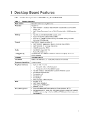
.../266/200 MHz DIMMs • Supports up to 2 GB of Intel® Desktop Board D845GVSR. Table 1. Four ports routed to RAM, resume on ring, wake from USB and PS/2 keyboard and mouse, and PME# wakeup. 9 1 Desktop Board Features Table 1 describes the major features of system memory with Ultra DMA-33 and ATA-66/100 support • One...
.../266/200 MHz DIMMs • Supports up to 2 GB of Intel® Desktop Board D845GVSR. Table 1. Four ports routed to RAM, resume on ring, wake from USB and PS/2 keyboard and mouse, and PME# wakeup. 9 1 Desktop Board Features Table 1 describes the major features of system memory with Ultra DMA-33 and ATA-66/100 support • One...
Product Guide
Page 14
... about: • The latest list of tested memory, http://support.intel.com/support/motherboards/desktop/ • SDRAM specifications, http://www.intel.com/technology/memory/pcsdram/spec/ • Installing memory, page 28 in Table 4. Up to configure the memory controller for normal operation. ✏ NOTE All memory components and DIMMs used with the desktop board must comply with DIMMs that support the...
... about: • The latest list of tested memory, http://support.intel.com/support/motherboards/desktop/ • SDRAM specifications, http://www.intel.com/technology/memory/pcsdram/spec/ • Installing memory, page 28 in Table 4. Up to configure the memory controller for normal operation. ✏ NOTE All memory components and DIMMs used with the desktop board must comply with DIMMs that support the...

Product Guide
Page 15
... connected to power either headphones or amplified speakers only. Desktop Board Features Intel® 845GV Chipset The Intel 845GV chipset consists of the following: • Intel 82845GV Graphics and Memory Controller Hub (GMCH) with AHA bus • Intel 82801DB I/O Controller Hub (ICH4) with AHA bus &#... codec The audio subsystem supports the following link for more information about : • Audio drivers and utilities, http://support.intel.com/support/motherboards/desktop/ • Installing a front panel audio solution, page 32 in ✏ NOTE The line out connector, located on...
... connected to power either headphones or amplified speakers only. Desktop Board Features Intel® 845GV Chipset The Intel 845GV chipset consists of the following: • Intel 82845GV Graphics and Memory Controller Hub (GMCH) with AHA bus • Intel 82801DB I/O Controller Hub (ICH4) with AHA bus &#... codec The audio subsystem supports the following link for more information about : • Audio drivers and utilities, http://support.intel.com/support/motherboards/desktop/ • Installing a front panel audio solution, page 32 in ✏ NOTE The line out connector, located on...

Product Guide
Page 19
...able to provide enough standby current to support multiple wake events from the following link: http://support.intel.com/support/motherboards/desktop/ 19 Figure 2. Desktop Board Features Chassis Intrusion The board supports a chassis security feature that can damage the power supply and/or effect ACPI S3 sleep ... front panel, the sleep state is standby power to provide adequate standby current when using this desktop board must be off . Failure to the system. This includes the memory modules and PCI bus connectors, even when the computer appears to be connected to -RAM) sleep...
...able to provide enough standby current to support multiple wake events from the following link: http://support.intel.com/support/motherboards/desktop/ 19 Figure 2. Desktop Board Features Chassis Intrusion The board supports a chassis security feature that can damage the power supply and/or effect ACPI S3 sleep ... front panel, the sleep state is standby power to provide adequate standby current when using this desktop board must be off . Failure to the system. This includes the memory modules and PCI bus connectors, even when the computer appears to be connected to -RAM) sleep...
Product Guide
Page 21
...the procedures described in this chapter. Do not use these connectors for using and modifying electronic equipment. 2 Installing and Replacing Desktop Board Components This chapter tells you open the computer or perform any of the midboard and front panel connectors provide operating voltage (+5... devices could cause damage to : • Install the I/O shield • Install and remove the desktop board • Install and remove a processor • Install and remove memory • Connect the IDE cable • Connect internal headers • Connect hardware control and power ...
...the procedures described in this chapter. Do not use these connectors for using and modifying electronic equipment. 2 Installing and Replacing Desktop Board Components This chapter tells you open the computer or perform any of the midboard and front panel connectors provide operating voltage (+5... devices could cause damage to : • Install the I/O shield • Install and remove the desktop board • Install and remove a processor • Install and remove memory • Connect the IDE cable • Connect internal headers • Connect hardware control and power ...
Product Guide
Page 28
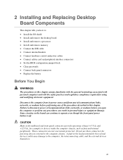
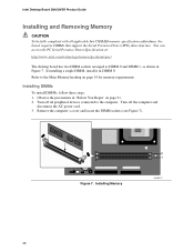
... 3. Installing Memory 0 1 OM16277 28 Intel Desktop Board D845GVSR Product Guide Installing and Removing Memory CAUTION To be fully compliant with all peripheral devices connected to the Main Memory heading on page 21. 2. Turn off all applicable Intel SDRAM memory specification addendums, the board requires DIMMs that...the precautions in "Before You Begin" on page 14 for memory requirements. You can access the PC Serial Presence Detect Specification at: http://www.intel.com/technology/memory/pcsdram/spec/ The desktop board has two DIMM sockets arranged as DIMM 0 and DIMM 1, ...
... 3. Installing Memory 0 1 OM16277 28 Intel Desktop Board D845GVSR Product Guide Installing and Removing Memory CAUTION To be fully compliant with all peripheral devices connected to the Main Memory heading on page 21. 2. Turn off all applicable Intel SDRAM memory specification addendums, the board requires DIMMs that...the precautions in "Before You Begin" on page 14 for memory requirements. You can access the PC Serial Presence Detect Specification at: http://www.intel.com/technology/memory/pcsdram/spec/ The desktop board has two DIMM sockets arranged as DIMM 0 and DIMM 1, ...

Product Guide
Page 29
...socket, and store it away from the computer. 4. Replace the computer's cover and reconnect the AC power cord. 29 Removing DIMMs To remove a memory module, follow these steps: 1. Remove the AGP card, if necessary. 6. Reinstall and reconnect any parts you removed or disconnected to the computer.... notches in the bottom edge of the DIMM into place. Hold the DIMM by the edges, lift it in Figure 7). 6. Installing and Replacing Desktop Board Components 4. Turn off the computer. 3. Replace the computer's cover and reconnect the AC power cord. When the DIMM is inserted, push down...
...socket, and store it away from the computer. 4. Replace the computer's cover and reconnect the AC power cord. 29 Removing DIMMs To remove a memory module, follow these steps: 1. Remove the AGP card, if necessary. 6. Reinstall and reconnect any parts you removed or disconnected to the computer.... notches in the bottom edge of the DIMM into place. Hold the DIMM by the edges, lift it in Figure 7). 6. Installing and Replacing Desktop Board Components 4. Turn off the computer. 3. Replace the computer's cover and reconnect the AC power cord. When the DIMM is inserted, push down...

Product Guide
Page 40
... werden. Entsorgen Sie verbrauchte Batterien den Anweisungen des Herstellers entsprechend. 40 Replace the battery with 3.3 VSB applied. Intel Desktop Board D845GVSR Product Guide Replacing the Battery A coin-cell battery (CR2032) powers the real-time clock and CMOS memory. Disposal of explosion if the battery is plugged in CMOS RAM (for example, the date and time...
... werden. Entsorgen Sie verbrauchte Batterien den Anweisungen des Herstellers entsprechend. 40 Replace the battery with 3.3 VSB applied. Intel Desktop Board D845GVSR Product Guide Replacing the Battery A coin-cell battery (CR2032) powers the real-time clock and CMOS memory. Disposal of explosion if the battery is plugged in CMOS RAM (for example, the date and time...
Product Guide
Page 45
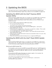
... BIOS Update utility you are updating the BIOS for creating a bootable flash memory update floppy that will be rebooted at : http://support.intel.com/support/motherboards/desktop/ Navigate to the D845GVSR page, click "[view] Latest BIOS updates", and select the Intel Iflash BIOS Update utility file. 45 Download the file to your hard drive where it...
... BIOS Update utility you are updating the BIOS for creating a bootable flash memory update floppy that will be rebooted at : http://support.intel.com/support/motherboards/desktop/ Navigate to the D845GVSR page, click "[view] Latest BIOS updates", and select the Intel Iflash BIOS Update utility file. 45 Download the file to your hard drive where it...
Product Guide
Page 46
...in drive A. The recovery process will automatically run the BIOS update process. 2. Boot the computer with the BIOS update diskette in flash memory • Update the language section of code available in the boot block area, there is complete, the monitor will not see Figure 12... amount of the BIOS Updating the BIOS CAUTION The AUTOEXEC.BAT file provided with the update utility before attempting a BIOS update. Intel Desktop Board D845GVSR Product Guide ✏ NOTE Review the instructions distributed with the update files updates the BIOS. Monitor the procedure by listening to ...
...in drive A. The recovery process will automatically run the BIOS update process. 2. Boot the computer with the BIOS update diskette in flash memory • Update the language section of code available in the boot block area, there is complete, the monitor will not see Figure 12... amount of the BIOS Updating the BIOS CAUTION The AUTOEXEC.BAT file provided with the update utility before attempting a BIOS update. Intel Desktop Board D845GVSR Product Guide ✏ NOTE Review the instructions distributed with the update files updates the BIOS. Monitor the procedure by listening to ...
Product Guide
Page 49
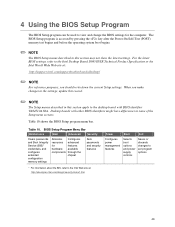
... the key after the Power-On Self-Test (POST) memory test begins and before the operating system boot begins. ✏ NOTE The BIOS Setup menus described in this section apply to the desktop board with other BIOS identifiers might have differences in this section ....intel.com/support/motherboards/desktop/ ✏ NOTE For reference purposes, you make changes to the settings, update this record. ✏ NOTE The Setup menus described in some of the Setup menu screens. For the latest BIOS settings, refer to the Intel Desktop Board D845GVSR Technical Product Specification or the Intel ...
... the key after the Power-On Self-Test (POST) memory test begins and before the operating system boot begins. ✏ NOTE The BIOS Setup menus described in this section apply to the desktop board with other BIOS identifiers might have differences in this section ....intel.com/support/motherboards/desktop/ ✏ NOTE For reference purposes, you make changes to the settings, update this record. ✏ NOTE The Setup menus described in some of the Setup menu screens. For the latest BIOS settings, refer to the Intel Desktop Board D845GVSR Technical Product Specification or the Intel ...

Product Guide
Page 51
... Boot BIOS Version VA84510A.86A.xxxx.xxx Exit Processor Type Processor Speed System Bus Speed System Memory Speed Intel(R) XXXXXXXXXXX X.XX GHz XXX MHz XXX MHz Cache RAM Total Memory Memory Bank 0 Memory Bank 1 Language System Time System Date XXX KB XXX MB XXX MB XXX MB [English...No options • Enabled (default) • Disabled Processor Speed No options System Bus Speed No options System Memory Speed No options Cache RAM No options Total Memory Memory Bank 0 Memory Bank 1 Language System Time System Date No options No options • English (default) • Espanol Hour...
... Boot BIOS Version VA84510A.86A.xxxx.xxx Exit Processor Type Processor Speed System Bus Speed System Memory Speed Intel(R) XXXXXXXXXXX X.XX GHz XXX MHz XXX MHz Cache RAM Total Memory Memory Bank 0 Memory Bank 1 Language System Time System Date XXX KB XXX MB XXX MB XXX MB [English...No options • Enabled (default) • Disabled Processor Speed No options System Bus Speed No options System Memory Speed No options Cache RAM No options Total Memory Memory Bank 0 Memory Bank 1 Language System Time System Date No options No options • English (default) • Espanol Hour...

Product Guide
Page 62
...; 512 KB • 1 MB (default) • 8 MB Description Amount of system memory available for use by the graphics device. Allows selecting the PCI video controller as the display device that will be active when the system boots. Table 22. Intel Desktop Board D845GVSR Product Guide Video Configuration Submenu Main Advanced Security Video Configuration Power Boot...
...; 512 KB • 1 MB (default) • 8 MB Description Amount of system memory available for use by the graphics device. Allows selecting the PCI video controller as the display device that will be active when the system boots. Table 22. Intel Desktop Board D845GVSR Product Guide Video Configuration Submenu Main Advanced Security Video Configuration Power Boot...

Product Guide
Page 64
... values may cause your system to malfunction! Allows override of detected memory frequency value. ISA Enable Bit PCI Latency Timer [Enabled] [32] Extended Configuration [Default] Chipset Memory Timing Control SDRAM Frequency SDRAM Timing Control SDRAM RAS Act. Set PCI latency time. Intel Desktop Board D845GVSR Product Guide Chipset Configuration Submenu Main Advanced Security Chipset Configuration Power...
... values may cause your system to malfunction! Allows override of detected memory frequency value. ISA Enable Bit PCI Latency Timer [Enabled] [32] Extended Configuration [Default] Chipset Memory Timing Control SDRAM Frequency SDRAM Timing Control SDRAM RAS Act. Set PCI latency time. Intel Desktop Board D845GVSR Product Guide Chipset Configuration Submenu Main Advanced Security Chipset Configuration Power...
Product Guide
Page 65
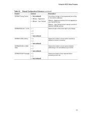
.... • 6 • 5 • Auto (default) SDRAM CAS# Latency • 3 • 2 Selects the number of clock cycles required to address a column in memory. • Auto (default) SDRAM RAS# to the memory detected. User Defined allows manual override of time required before accessing a new row. • Auto (default) 65 User Defined Auto allows timings...
.... • 6 • 5 • Auto (default) SDRAM CAS# Latency • 3 • 2 Selects the number of clock cycles required to address a column in memory. • Auto (default) SDRAM RAS# to the memory detected. User Defined allows manual override of time required before accessing a new row. • Auto (default) 65 User Defined Auto allows timings...

Product Guide
Page 74
...the factory defaults. Exit Discarding Changes Exits without exiting Setup. Save Custom Defaults Saves the current values as custom defaults. If this memory is used . 74 If no custom defaults are used to exit the BIOS Setup program, saving changes, and loading and saving ...33. Normally, the BIOS reads the Setup values from flash memory. Load Custom Defaults Loads the custom defaults for Setup options. Discard Changes Discards changes without saving any changes made in CMOS SRAM. Intel Desktop Board D845GVSR Product Guide Exit Menu Main Advanced Security Power Boot Exit Exit...
...the factory defaults. Exit Discarding Changes Exits without exiting Setup. Save Custom Defaults Saves the current values as custom defaults. If this memory is used . 74 If no custom defaults are used to exit the BIOS Setup program, saving changes, and loading and saving ...33. Normally, the BIOS reads the Setup values from flash memory. Load Custom Defaults Loads the custom defaults for Setup options. Discard Changes Discards changes without saving any changes made in CMOS SRAM. Intel Desktop Board D845GVSR Product Guide Exit Menu Main Advanced Security Power Boot Exit Exit...


