Product Guide
Page 5
Contents 1 Desktop Board Features Desktop Board Components 11 Processor ...13 Main Memory ...14 Intel® 845GV Chipset ...15 Audio Subsystem ...15 LAN Subsystem (Optional 16 LAN Subsystem Software 16 RJ-45 LAN Connector LEDs ... Desktop Board 25 Installing and Removing a Processor 26 Installing a Processor 26 Installing the Processor Fan Heatsink 26 Connecting the Processor Fan Heatsink Cable 27 Removing a Processor 27 Installing and Removing Memory 28 Installing DIMMs ...28 Removing DIMMs ...29 Connecting the IDE Cable 30 Connecting Internal Headers 31 Connecting the Front Panel ...
Contents 1 Desktop Board Features Desktop Board Components 11 Processor ...13 Main Memory ...14 Intel® 845GV Chipset ...15 Audio Subsystem ...15 LAN Subsystem (Optional 16 LAN Subsystem Software 16 RJ-45 LAN Connector LEDs ... Desktop Board 25 Installing and Removing a Processor 26 Installing a Processor 26 Installing the Processor Fan Heatsink 26 Connecting the Processor Fan Heatsink Cable 27 Removing a Processor 27 Installing and Removing Memory 28 Installing DIMMs ...28 Removing DIMMs ...29 Connecting the IDE Cable 30 Connecting Internal Headers 31 Connecting the Front Panel ...
Product Guide
Page 6
Intel Desktop Board D845GVSR Product Guide Connecting Add-In Card and Peripheral Interface Connectors 36 Setting the BIOS Configuration Jumper Block 37 Clearing Passwords ...38 Back Panel Connectors ...39 Replacing the Battery ...40 3 Updating the BIOS Updating the BIOS with the Intel® Express BIOS Update Utility 45 Updating the BIOS with the Intel...Hard Disk Drives Submenu 71 Removable Devices Submenu 72 ATAPI CD-ROM Drives 73 Exit Menu ...74 5 Desktop Board Resources Memory Map ...75 DMA Channels ...75 Interrupts ...76 A Error Messages and Indicators BIOS Beep Codes ...77 BIOS ...
Intel Desktop Board D845GVSR Product Guide Connecting Add-In Card and Peripheral Interface Connectors 36 Setting the BIOS Configuration Jumper Block 37 Clearing Passwords ...38 Back Panel Connectors ...39 Replacing the Battery ...40 3 Updating the BIOS Updating the BIOS with the Intel® Express BIOS Update Utility 45 Updating the BIOS with the Intel...Hard Disk Drives Submenu 71 Removable Devices Submenu 72 ATAPI CD-ROM Drives 73 Exit Menu ...74 5 Desktop Board Resources Memory Map ...75 DMA Channels ...75 Interrupts ...76 A Error Messages and Indicators BIOS Beep Codes ...77 BIOS ...
Product Guide
Page 7
... Connectors 34 11. Installing the I/O Shield 24 4. Connecting the IDE Cable 30 9. Internal Headers ...31 10. Back Panel Connectors 39 14. Desktop Board Mounting Screw Holes 25 5. Installing Memory...28 8. Add-in Card and Peripheral Interface Connectors 36 12. Removing the Battery from the Desktop Board 43 vii Connecting the Processor Fan Heatsink Cable to the Processor...
... Connectors 34 11. Installing the I/O Shield 24 4. Connecting the IDE Cable 30 9. Internal Headers ...31 10. Back Panel Connectors 39 14. Desktop Board Mounting Screw Holes 25 5. Installing Memory...28 8. Add-in Card and Peripheral Interface Connectors 36 12. Removing the Battery from the Desktop Board 43 vii Connecting the Processor Fan Heatsink Cable to the Processor...
Product Guide
Page 9
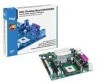
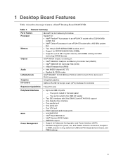
1 Desktop Board Features Table 1 describes the major features of : • Intel® 82845GV Grahpics and Memory Controller Hub (GMCH) • Intel® 82801DB I/O Controller Hub (ICH4) • 4 Mbit Firmware Hub (FWH) • Intel 845GV chipset (AC '97) • Realtek ALC202A codec Intel® 82562ET 10/100 Mbit/sec Platform LAN Connect (PLC) device and ..., and PME# wakeup. 9 Two ports routed to the USB 2.0 header • Two IDE interfaces with DIMMs utilizing 512 Mbit technology DRAM devices Intel® 845GV chipset, consisting of Intel® Desktop Board D845GVSR. Table 1.
1 Desktop Board Features Table 1 describes the major features of : • Intel® 82845GV Grahpics and Memory Controller Hub (GMCH) • Intel® 82801DB I/O Controller Hub (ICH4) • 4 Mbit Firmware Hub (FWH) • Intel 845GV chipset (AC '97) • Realtek ALC202A codec Intel® 82562ET 10/100 Mbit/sec Platform LAN Connect (PLC) device and ..., and PME# wakeup. 9 Two ports routed to the USB 2.0 header • Two IDE interfaces with DIMMs utilizing 512 Mbit technology DRAM devices Intel® 845GV chipset, consisting of Intel® Desktop Board D845GVSR. Table 1.

Product Guide
Page 15
...are connected to the following link or pages for more information about: • Audio drivers and utilities, http://support.intel.com/support/motherboards/desktop/ • Installing a front panel audio solution, page 32 in ✏ NOTE The line out connector, located on the back panel,... this output. Mic in Chapter 2 15 Desktop Board Features Intel® 845GV Chipset The Intel 845GV chipset consists of the following audio interfaces: • ATAPI-style connectors: - Line in - CD-ROM • Front panel audio connector • Back panel connectors: - Line out - Auxiliary line ...
...are connected to the following link or pages for more information about: • Audio drivers and utilities, http://support.intel.com/support/motherboards/desktop/ • Installing a front panel audio solution, page 32 in ✏ NOTE The line out connector, located on the back panel,... this output. Mic in Chapter 2 15 Desktop Board Features Intel® 845GV Chipset The Intel 845GV chipset consists of the following audio interfaces: • ATAPI-style connectors: - Line in - CD-ROM • Front panel audio connector • Back panel connectors: - Line out - Auxiliary line ...
Product Guide
Page 16
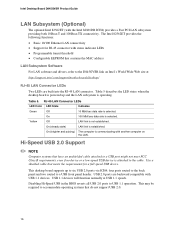
... devices will function normally at : http://support.intel.com/support/motherboards/desktop/ RJ-45 LAN Connector LEDs Two LEDs are backward compatible with the Intel 82801DB ICH4) provides a Fast PCI LAN subsystem providing both 10Base-T and 100Base-TX connectivity. This may be required to accommodate operating systems ...The computer is operating. Disabling Hi-Speed USB in the BIOS reverts all USB 2.0 ports to a USB front panel header. Table 5. USB 2.0 ports are built into the RJ-45 LAN connector. Intel Desktop Board D845GVSR Product Guide LAN Subsystem (Optional) The optional...
... devices will function normally at : http://support.intel.com/support/motherboards/desktop/ RJ-45 LAN Connector LEDs Two LEDs are backward compatible with the Intel 82801DB ICH4) provides a Fast PCI LAN subsystem providing both 10Base-T and 100Base-TX connectivity. This may be required to accommodate operating systems ...The computer is operating. Disabling Hi-Speed USB in the BIOS reverts all USB 2.0 ports to a USB front panel header. Table 5. USB 2.0 ports are built into the RJ-45 LAN connector. Intel Desktop Board D845GVSR Product Guide LAN Subsystem (Optional) The optional...

Product Guide
Page 19
... supplies used with this feature can be connected to the chassis intrusion header on the desktop board. Instantly Available PC technology enables the board to enter the ACPI S3 (Suspend-to...support multiple wake events from the following link: http://support.intel.com/support/motherboards/desktop/ 19 Desktop Board Features Chassis Intrusion The board supports a chassis security feature that can damage the power ...to -RAM) sleep state. The security feature uses a mechanical switch on the front panel, the sleep state is standby power to the system. When signaled by the LED turning...
... supplies used with this feature can be connected to the chassis intrusion header on the desktop board. Instantly Available PC technology enables the board to enter the ACPI S3 (Suspend-to...support multiple wake events from the following link: http://support.intel.com/support/motherboards/desktop/ 19 Desktop Board Features Chassis Intrusion The board supports a chassis security feature that can damage the power ...to -RAM) sleep state. The security feature uses a mechanical switch on the front panel, the sleep state is standby power to the system. When signaled by the LED turning...
Product Guide
Page 21
...; Install and remove the desktop board • Install and remove a processor • Install and remove memory • Connect the IDE cable • Connect internal headers • Connect hardware control and power cables • Connect add-in card and peripheral interface connectors • Set the BIOS configuration jumper block • Clear passwords • Connect back panel connectors • Replace...
...; Install and remove the desktop board • Install and remove a processor • Install and remove memory • Connect the IDE cable • Connect internal headers • Connect hardware control and power cables • Connect add-in card and peripheral interface connectors • Set the BIOS configuration jumper block • Clear passwords • Connect back panel connectors • Replace...
Product Guide
Page 31
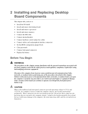
Internal Headers OM16279 31 A F 1 2 3 4 5 6 7 9 10 J8A1 J7A1 B J6B1 E 1 2 3 4 5 6 7 8 10 J9F2 C 1 2 3 4 5 6 7 8 9 J9G1 13 J8H3 D Item A B C D E F Description Auxiliary-in CD-in Front panel Power LED Front panel USB 2.0 Front panel audio Figure 9. Installing and Replacing Desktop Board Components Connecting Internal Headers Follow the instructions below to connect the USB 2.0 solution, power LED, front panel, and audio solution. See Figure 9 for pin assignments.
Internal Headers OM16279 31 A F 1 2 3 4 5 6 7 9 10 J8A1 J7A1 B J6B1 E 1 2 3 4 5 6 7 8 10 J9F2 C 1 2 3 4 5 6 7 8 9 J9G1 13 J8H3 D Item A B C D E F Description Auxiliary-in CD-in Front panel Power LED Front panel USB 2.0 Front panel audio Figure 9. Installing and Replacing Desktop Board Components Connecting Internal Headers Follow the instructions below to connect the USB 2.0 solution, power LED, front panel, and audio solution. See Figure 9 for pin assignments.

Product Guide
Page 32
... header (J8A1). 4. Install a correctly keyed and shielded front panel audio cable. 6. Table 6 shows the pin assignments for the front panel audio header. Remove the three jumpers from the header (this disables the back panel audio connectors). 5. Table 7. Intel Desktop Board D845GVSR Product Guide Connecting the Front Panel Header Before connecting the front panel header, observe the precautions in "Before You Begin...
... header (J8A1). 4. Install a correctly keyed and shielded front panel audio cable. 6. Table 6 shows the pin assignments for the front panel audio header. Remove the three jumpers from the header (this disables the back panel audio connectors). 5. Table 7. Intel Desktop Board D845GVSR Product Guide Connecting the Front Panel Header Before connecting the front panel header, observe the precautions in "Before You Begin...
Product Guide
Page 33
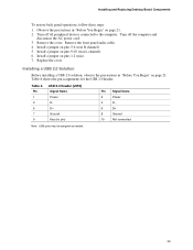
... Replace the cover. Observe the precautions in "Before You Begin" on pins 5-6 (rear R channel). 5. Turn off all peripheral devices connected to the computer. Install a jumper on page 21. 2. Installing a USB 2.0 Solution Before installing a USB 2.0 solution, observe the ... Signal Name 2 Power 4 D- 6 D+ 8 Ground 10 Not connected Note: USB ports may be assigned as needed. 33 Installing and Replacing Desktop Board Components To restore back panel operations, follow these steps: 1. Remove the front panel audio cable. 4. Table 8. Table 8 shows the pin assignments for...
... Replace the cover. Observe the precautions in "Before You Begin" on pins 5-6 (rear R channel). 5. Turn off all peripheral devices connected to the computer. Install a jumper on page 21. 2. Installing a USB 2.0 Solution Before installing a USB 2.0 solution, observe the ... Signal Name 2 Power 4 D- 6 D+ 8 Ground 10 Not connected Note: USB ports may be assigned as needed. 33 Installing and Replacing Desktop Board Components To restore back panel operations, follow these steps: 1. Remove the front panel audio cable. 4. Table 8. Table 8 shows the pin assignments for...

Product Guide
Page 39
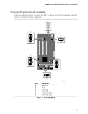
Installing and Replacing Desktop Board Components Back Panel Connectors ✏ NOTE The line out connector, located on the back panel, is designed to this output. AB C DE F GH I JK Item A B C D E F G H I J K Description PS/2 mouse port PS/2 keyboard port USB 2.0 ports Serial port ... VGA port RJ-45 (optional) USB 2.0 ports Mic in Audio line out Audio line in Figure 13. Back Panel Connectors OM16283 39 Figure 13 shows the back panel connectors. Poor audio quality may occur if passive (non-amplified) speakers are connected to power either headphones or amplified speakers only.
Installing and Replacing Desktop Board Components Back Panel Connectors ✏ NOTE The line out connector, located on the back panel, is designed to this output. AB C DE F GH I JK Item A B C D E F G H I J K Description PS/2 mouse port PS/2 keyboard port USB 2.0 ports Serial port ... VGA port RJ-45 (optional) USB 2.0 ports Mic in Audio line out Audio line in Figure 13. Back Panel Connectors OM16283 39 Figure 13 shows the back panel connectors. Poor audio quality may occur if passive (non-amplified) speakers are connected to power either headphones or amplified speakers only.
User Guide
Page 34
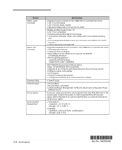
... label, you need to 35 o C - Supports ACPI technology - Supports LAN wake capabilities Intel ® 82562ET physical layer interface device • Basic 10/100 Ethernet LAN connectivity • Supports RJ-45 connector with independent and variable sampling rate • Four analog line...compatible • Industry Leading Mixed Signal Technology • 18-bit stereo full-duplex Codec with status indicator LEDs on the back panel • Full device driver compatibility • ACPI support • Programmable transit threshold • Configuration EEPROM that contains the MAC...
... label, you need to 35 o C - Supports ACPI technology - Supports LAN wake capabilities Intel ® 82562ET physical layer interface device • Basic 10/100 Ethernet LAN connectivity • Supports RJ-45 connector with independent and variable sampling rate • Four analog line...compatible • Industry Leading Mixed Signal Technology • 18-bit stereo full-duplex Codec with status indicator LEDs on the back panel • Full device driver compatibility • ACPI support • Programmable transit threshold • Configuration EEPROM that contains the MAC...


