
Product Specification
Page 6
Intel Desktop Board D101GGC Technical Product Specification 2.9 Mechanical Considerations 46 2.9.1 Form Factor 46 2.9.2 I/O Shield...47 2.10 Electrical Considerations 48 2.10.1 DC Loading...48 2.10.2 Add-in Board Considerations 48 2.10.3 Fan Connector Current Capability 49 2.10.4 Power Supply Considerations 49 2.11 Thermal Considerations 50 2.12 Reliability...52 2.13 Environmental ...53 2.14 Regulatory Compliance 54 2.14...
Intel Desktop Board D101GGC Technical Product Specification 2.9 Mechanical Considerations 46 2.9.1 Form Factor 46 2.9.2 I/O Shield...47 2.10 Electrical Considerations 48 2.10.1 DC Loading...48 2.10.2 Add-in Board Considerations 48 2.10.3 Fan Connector Current Capability 49 2.10.4 Power Supply Considerations 49 2.11 Thermal Considerations 50 2.12 Reliability...52 2.13 Environmental ...53 2.14 Regulatory Compliance 54 2.14...
Product Specification
Page 10
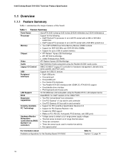
... on PCI, RS-232, front panel, PS/2 devices, and USB ports • Voltage sense to detect out of range power supply voltages • Thermal sense to detect out of the board. Intel Desktop Board D101GGC Technical Product Specification 1.1 Overview 1.1.1 Feature Summary Table 1 summarizes the major features of range thermal values • Three fan connectors...
... on PCI, RS-232, front panel, PS/2 devices, and USB ports • Voltage sense to detect out of range power supply voltages • Thermal sense to detect out of the board. Intel Desktop Board D101GGC Technical Product Specification 1.1 Overview 1.1.1 Feature Summary Table 1 summarizes the major features of range thermal values • Three fan connectors...
Product Specification
Page 14
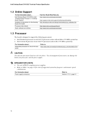
... processors for a list of unsupported processors can damage the board, the processor, and the power supply. # INTEGRATOR'S NOTE • Use only ATX12V-compliant power supplies. • Refer to Table 3 on page 15 for the D101GGC board Refer to: http://www.intel.com/design/motherbd/gc/gc_documentation.htm CAUTION Use only the processors listed on web site...
... processors for a list of unsupported processors can damage the board, the processor, and the power supply. # INTEGRATOR'S NOTE • Use only ATX12V-compliant power supplies. • Refer to Table 3 on page 15 for the D101GGC board Refer to: http://www.intel.com/design/motherbd/gc/gc_documentation.htm CAUTION Use only the processors listed on web site...
Product Specification
Page 18
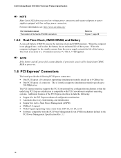
Intel Desktop Board D101GGC Technical Product Specification NOTE Many Serial ATA drives use new low-voltage power connectors and require adaptors or power supplies equipped with 3.3 VSB applied. When the computer is not plugged into CMOS RAM at 25 ºC with low-voltage power connectors. For more ...information about The location of three years. When the computer is compatible with the PCI Power Management Event (PME) mechanism defined in , the standby current from the power supply extends the life of the PCI Express interface include the following PCI Express connectors: •...
Intel Desktop Board D101GGC Technical Product Specification NOTE Many Serial ATA drives use new low-voltage power connectors and require adaptors or power supplies equipped with 3.3 VSB applied. When the computer is not plugged into CMOS RAM at 25 ºC with low-voltage power connectors. For more ...information about The location of three years. When the computer is compatible with the PCI Power Management Event (PME) mechanism defined in , the standby current from the power supply extends the life of the PCI Express interface include the following PCI Express connectors: •...

Product Specification
Page 23
... acceptable values • Thermally monitored closed position. The features of the chassis intrusion connector Refer to be implemented using Intel® Desktop Utilities, LANDesk* software, or thirdparty software. For information about The location of the chassis intrusion connector... mechanical switch is in the closed -loop fan control, for direct monitoring of processor temperature and ambient temperature sensing • Power supply monitoring of the fan connectors Refer to implement hardware monitoring and fan control. The SMSC SCH5017 I /O controller include: •...
... acceptable values • Thermally monitored closed position. The features of the chassis intrusion connector Refer to be implemented using Intel® Desktop Utilities, LANDesk* software, or thirdparty software. For information about The location of the chassis intrusion connector... mechanical switch is in the closed -loop fan control, for direct monitoring of processor temperature and ambient temperature sensing • Power supply monitoring of the fan connectors Refer to implement hardware monitoring and fan control. The SMSC SCH5017 I /O controller include: •...
Product Specification
Page 25
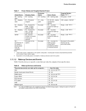
... Events Table 8 lists the devices or specific events that can wake the computer from this option to Power On will enable a wake-up devices used in boards and peripherals powered by the system chassis' power supply. 2. Table 8. Full power > 30 W G1 - Processor stopped C1 - sleeping state G2/S5 S3 - Context saved to the system. D3...
... Events Table 8 lists the devices or specific events that can wake the computer from this option to Power On will enable a wake-up devices used in boards and peripherals powered by the system chassis' power supply. 2. Table 8. Full power > 30 W G1 - Processor stopped C1 - sleeping state G2/S5 S3 - Context saved to the system. D3...
Product Specification
Page 26
...ACPI support. Failure to access the computer when it is in a power-managed state. The total amount of standby current required depends on Ring enables telephony devices to do so can damage the power supply. In addition, software, drivers, and peripherals must fully support ACPI... Support CAUTION Ensure that the power supply provides adequate +5 V standby current if LAN wake capabilities and Instantly Available PC technology features are used depends on the type of telephony device (external or internal). The method used . Intel Desktop Board D101GGC Technical Product Specification NOTE The ...
...ACPI support. Failure to access the computer when it is in a power-managed state. The total amount of standby current required depends on Ring enables telephony devices to do so can damage the power supply. In addition, software, drivers, and peripherals must fully support ACPI... Support CAUTION Ensure that the power supply provides adequate +5 V standby current if LAN wake capabilities and Instantly Available PC technology features are used depends on the type of telephony device (external or internal). The method used . Intel Desktop Board D101GGC Technical Product Specification NOTE The ...
Product Specification
Page 27
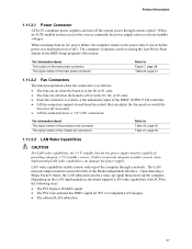
...the following ways: • The PCI Express WAKE# signal • The PCI Conventional bus PME# signal for the power supply must be set using the Last Power State feature in the BIOS Setup program's Boot menu. Depending on or off or in the S0 or S1 state...to provide adequate standby current when implementing LAN wake capabilities can damage the power supply. The LAN network adapter monitors network traffic at the Media Independent Interface. Product Description 1.11.2.1 Power Connector ATX12V-compliant power supplies can turn off ). LAN wake capabilities enable remote wake-up the computer...
...the following ways: • The PCI Express WAKE# signal • The PCI Conventional bus PME# signal for the power supply must be set using the Last Power State feature in the BIOS Setup program's Boot menu. Depending on or off or in the S0 or S1 state...to provide adequate standby current when implementing LAN wake capabilities can damage the power supply. The LAN network adapter monitors network traffic at the Media Independent Interface. Product Description 1.11.2.1 Power Connector ATX12V-compliant power supplies can turn off ). LAN wake capabilities enable remote wake-up the computer...
Product Specification
Page 28
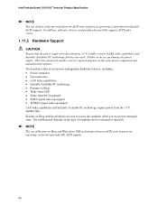
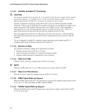
... board supports the PCI Bus Power Management Interface Specification. Add-in boards that also support this specification can participate in power management and can be capable of a USB peripheral that can damage the power supply. Intel Desktop Board D101GGC Technical Product Specification 1.11.2.4 ...Instantly Available PC Technology CAUTION For Instantly Available PC technology, the +5 V standby line for the power supply must be used to wake the computer. ...
... board supports the PCI Bus Power Management Interface Specification. Add-in boards that also support this specification can participate in power management and can be capable of a USB peripheral that can damage the power supply. Intel Desktop Board D101GGC Technical Product Specification 1.11.2.4 ...Instantly Available PC Technology CAUTION For Instantly Available PC technology, the +5 V standby line for the power supply must be used to wake the computer. ...

Product Specification
Page 41
... 3 +12 V Pin Signal Name 2 Ground 4 +12 V 41 Main Power Connector Pin Signal Name 1 +3.3 V 2 +3.3 V 3 Ground 4 +5 V 5 Ground 6 +5 V 7 Ground 8 PWRGD (Power Good) 9 +5 V (Standby) 10 +12 V 11 +12 V (Note) 12 2 x 12 connector detect (Note) Pin Signal Name 13 +3.3 V 14 -12 V 15 Ground 16 PS-ON# (power supply remote on Intel Desktop boards. The board supports the use of the...
... 3 +12 V Pin Signal Name 2 Ground 4 +12 V 41 Main Power Connector Pin Signal Name 1 +3.3 V 2 +3.3 V 3 Ground 4 +5 V 5 Ground 6 +5 V 7 Ground 8 PWRGD (Power Good) 9 +5 V (Standby) 10 +12 V 11 +12 V (Note) 12 2 x 12 connector detect (Note) Pin Signal Name 13 +3.3 V 14 -12 V 15 Ground 16 PS-ON# (power supply remote on Intel Desktop boards. The board supports the use of the...

Product Specification
Page 44
... USB 2.0 specification for Front Panel USB Connectors 44 Power (+5 V DC) One D− USB Port D+ 1 2 3 4 5 6 Power (+5 V DC) D− One USB D+ Port Ground 7 8 Ground Key (no pin) 10 No Connect OM15963 Figure 9. Intel Desktop Board D101GGC Technical Product Specification NOTE The colors listed in Table ...26 and Table 27 are product- Actual LED colors are suggested colors only. The switch must pull the SW_ON# pin to ground for at least 50 ms to signal the power supply...
... USB 2.0 specification for Front Panel USB Connectors 44 Power (+5 V DC) One D− USB Port D+ 1 2 3 4 5 6 Power (+5 V DC) D− One USB D+ Port Ground 7 8 Ground Key (no pin) 10 No Connect OM15963 Figure 9. Intel Desktop Board D101GGC Technical Product Specification NOTE The colors listed in Table ...26 and Table 27 are product- Actual LED colors are suggested colors only. The switch must pull the SW_ON# pin to ground for at least 50 ms to signal the power supply...
Product Specification
Page 48
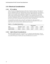
... but are based on the system's usage model and not necessarily tied to provide 2 A (average) of +5 V current for each add-in board. The selection of a power supply at : +12 V -12 V 18.1 A 0.05 A 25 A 0.1 A +5 VSB 1.8 A 2.3 A 2.10.2 Add-in Board Considerations The board is dependent on ... a light load placed on the board that is based on the board that impact its power delivery subsystems. The analysis does not include PCI add-in cards. Intel Desktop Board D101GGC Technical Product Specification 2.10 Electrical Considerations 2.10.1 DC Loading Table 29 lists the DC loading...
... but are based on the system's usage model and not necessarily tied to provide 2 A (average) of +5 V current for each add-in board. The selection of a power supply at : +12 V -12 V 18.1 A 0.05 A 25 A 0.1 A +5 VSB 1.8 A 2.3 A 2.10.2 Add-in Board Considerations The board is dependent on ... a light load placed on the board that is based on the board that impact its power delivery subsystems. The analysis does not include PCI add-in cards. Intel Desktop Board D101GGC Technical Product Specification 2.10 Electrical Considerations 2.10.1 DC Loading Table 29 lists the DC loading...

Product Specification
Page 49
... Current Capability Fan Connector Processor fan Front chassis fan Rear chassis fan Maximum Available Current 3000 mA 1500 mA 1500 mA 2.10.4 Power Supply Considerations CAUTION The +5 V standby line for use with the following recommendations found in onboard component damage that will depend on the... of the +5 VSB line • All timing parameters • All voltage tolerances 49 Connecting the processor fan to the power usage values listed in Table 29 when selecting a power supply for the power supply must be connected to the processor fan connector, not to do so can damage the...
... Current Capability Fan Connector Processor fan Front chassis fan Rear chassis fan Maximum Available Current 3000 mA 1500 mA 1500 mA 2.10.4 Power Supply Considerations CAUTION The +5 V standby line for use with the following recommendations found in onboard component damage that will depend on the... of the +5 VSB line • All timing parameters • All voltage tolerances 49 Connecting the processor fan to the power usage values listed in Table 29 when selecting a power supply for the power supply must be connected to the processor fan connector, not to do so can damage the...
Product Specification
Page 62
...processor and memory configuration Configures advanced features available through the chipset Sets passwords and security features Power Boot Configures power management features and power supply controls Selects boot options Exit Saves or discards changes to configure the system. Autoconfiguration lets a...the high capacities typically available today, hard drives are considered to optimize capacity and performance. Table 38. Intel Desktop Board D101GGC Technical Product Specification Table 37 lists the BIOS Setup program menu features. The interface also supports second-...
...processor and memory configuration Configures advanced features available through the chipset Sets passwords and security features Power Boot Configures power management features and power supply controls Selects boot options Exit Saves or discards changes to configure the system. Autoconfiguration lets a...the high capacities typically available today, hard drives are considered to optimize capacity and performance. Table 38. Intel Desktop Board D101GGC Technical Product Specification Table 37 lists the BIOS Setup program menu features. The interface also supports second-...

Intel Desktop Board D101GGC Product Guide English
Page 5
... and IDE Auto Configuration 17 PCI and PCI Express Auto Configuration 17 Security Passwords ...18 Chassis Intrusion...18 Power Management Features 18 ACPI...18 Power Connectors...18 Fan Connectors...19 Suspend to RAM (Instantly Available PC Technology 19 Wake from USB...20 Wake ...21 Battery...21 Real-Time Clock...21 2 Installing and Replacing Desktop Board Components Before You Begin ...23 Installation Precautions ...24 Prevent Power Supply Overload 24 Observe Safety and Regulatory Requirements 24 Installing the I/O Shield ...25 Installing and Removing the Desktop Board 26 Installing and ...
... and IDE Auto Configuration 17 PCI and PCI Express Auto Configuration 17 Security Passwords ...18 Chassis Intrusion...18 Power Management Features 18 ACPI...18 Power Connectors...18 Fan Connectors...19 Suspend to RAM (Instantly Available PC Technology 19 Wake from USB...20 Wake ...21 Battery...21 Real-Time Clock...21 2 Installing and Replacing Desktop Board Components Before You Begin ...23 Installation Precautions ...24 Prevent Power Supply Overload 24 Observe Safety and Regulatory Requirements 24 Installing the I/O Shield ...25 Installing and Removing the Desktop Board 26 Installing and ...
Intel Desktop Board D101GGC Product Guide English
Page 7
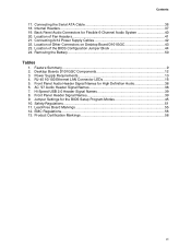
Power Supply Requirements 13 4. Hi-Speed USB 2.0 Header Signal Names 39 8. Front Panel Header Signal Names 39 9. Removing the Battery 50 Tables 1. Jumper Settings for High Definition Audio 38 6. Contents 17. Desktop Boards D101GGC Components 12 3. Front Panel Audio Header Signal Names for ...38 7. Feature Summary ...9 2. Location of Other Connectors on Desktop Board D101GGC 43 23. RJ-45 10/100 Ethernet LAN Connector LEDs 16 5. Connecting the Serial ATA Cable 36 18. Connecting 2x12 Power Supply Cables 42 22. Back Panel Audio Connectors for Flexible 6-Channel Audio ...
Power Supply Requirements 13 4. Hi-Speed USB 2.0 Header Signal Names 39 8. Front Panel Header Signal Names 39 9. Removing the Battery 50 Tables 1. Jumper Settings for High Definition Audio 38 6. Contents 17. Desktop Boards D101GGC Components 12 3. Front Panel Audio Header Signal Names for ...38 7. Feature Summary ...9 2. Location of Other Connectors on Desktop Board D101GGC 43 23. RJ-45 10/100 Ethernet LAN Connector LEDs 16 5. Connecting the Serial ATA Cable 36 18. Connecting 2x12 Power Supply Cables 42 22. Back Panel Audio Connectors for Flexible 6-Channel Audio ...
Intel Desktop Board D101GGC Product Guide English
Page 13
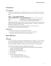
.... Desktop Board Features Processor CAUTION Failure to use the appropriate power supply (below : ⎯ Up to 1.0 GB utilizing 256 Mb technology ⎯ Up to configure the memory controller for desktop board D101GGC is located on installing or upgrading the processor, page 27 ...; The location of 13 A continuous and 16.5 A peak current for 10 ms ATX12V (version 2.0 or greater) compliant power supply Desktop board D101GGC supports an Intel processor in the LGA775 package. Processors are not included with DIMMs that support the Serial Presence Detect (SPD) data structure....
.... Desktop Board Features Processor CAUTION Failure to use the appropriate power supply (below : ⎯ Up to 1.0 GB utilizing 256 Mb technology ⎯ Up to configure the memory controller for desktop board D101GGC is located on installing or upgrading the processor, page 27 ...; The location of 13 A continuous and 16.5 A peak current for 10 ms ATX12V (version 2.0 or greater) compliant power supply Desktop board D101GGC supports an Intel processor in the LGA775 package. Processors are not included with DIMMs that support the Serial Presence Detect (SPD) data structure....
Intel Desktop Board D101GGC Product Guide English
Page 19
...and PCI bus connectors, even when the computer appears to support multiple wake events from the PCI and/or USB buses exceeds power supply capacity, the desktop board may lose register settings stored in memory. If the standby current necessary to be off . While in... For Instantly Available PC technology, the 5 V standby line for the location of delivering adequate +5 V standby current. Power supplies used with this feature can damage the power supply and/or effect ACPI S3 sleep state functionality. Desktop Board Features Fan Connectors The desktop board has a 4-pin processor ...
...and PCI bus connectors, even when the computer appears to support multiple wake events from the PCI and/or USB buses exceeds power supply capacity, the desktop board may lose register settings stored in memory. If the standby current necessary to be off . While in... For Instantly Available PC technology, the 5 V standby line for the location of delivering adequate +5 V standby current. Power supplies used with this feature can damage the power supply and/or effect ACPI S3 sleep state functionality. Desktop Board Features Fan Connectors The desktop board has a 4-pin processor ...
Intel Desktop Board D101GGC Product Guide English
Page 24
Intel Desktop Board D101GGC Product Guide Installation Precautions When you install and test the Intel desktop board, observe all the modules within the computer is less than the output current rating of each of noncompliance with the chassis and associated modules. To avoid overloading the power supply, make sure that instruct you increase safety risk and...
Intel Desktop Board D101GGC Product Guide Installation Precautions When you install and test the Intel desktop board, observe all the modules within the computer is less than the output current rating of each of noncompliance with the chassis and associated modules. To avoid overloading the power supply, make sure that instruct you increase safety risk and...
Intel Desktop Board D101GGC Product Guide English
Page 34
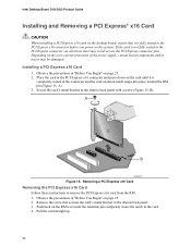
... precautions in "Before You Begin" on the RM lever until it is fully seated in "Before You Begin" on the over-current protection of the power supply, certain board components and/or traces may result across the PCI Express connector pins. A C B OM18214 Figure 15. Push back on page 23. ... pin completely clears the notch in the connector and the card retention notch snaps into place around the RM pin (Figure 15, A). 3. Intel Desktop Board D101GGC Product Guide Installing and Removing a PCI Express* x16 Card CAUTION When installing a PCI Express x16 card on the desktop board, ensure that ...
... precautions in "Before You Begin" on the RM lever until it is fully seated in "Before You Begin" on the over-current protection of the power supply, certain board components and/or traces may result across the PCI Express connector pins. A C B OM18214 Figure 15. Push back on page 23. ... pin completely clears the notch in the connector and the card retention notch snaps into place around the RM pin (Figure 15, A). 3. Intel Desktop Board D101GGC Product Guide Installing and Removing a PCI Express* x16 Card CAUTION When installing a PCI Express x16 card on the desktop board, ensure that ...


