Product Guide
Page 5
Contents 1 Desktop Board Features Supported Operating Systems 11 Desktop Board Components 12 Processor ...14 Main Memory...15 Intel® X38 Express Chipset 15 Audio Subsystem 16 LAN Subsystem 16 USB 2.0 Support 17 Enhanced IDE Interface 18 Serial ATA...18 Legacy I/O ...18 Expandability...18 BIOS ...19 Serial ATA and IDE Auto Configuration 19 ...
Contents 1 Desktop Board Features Supported Operating Systems 11 Desktop Board Components 12 Processor ...14 Main Memory...15 Intel® X38 Express Chipset 15 Audio Subsystem 16 LAN Subsystem 16 USB 2.0 Support 17 Enhanced IDE Interface 18 Serial ATA...18 Legacy I/O ...18 Expandability...18 BIOS ...19 Serial ATA and IDE Auto Configuration 19 ...
Product Guide
Page 6
... a PCI Express x16 Card 47 Connecting the IDE Cable 48 Connecting the Serial ATA (SATA) Cables 49 Connecting to the Internal Headers 50 Front Panel Audio Header 51 HD Audio Link Header 51 Consumer IR (CIR) Headers 51 Chassis Intrusion Header 52 IEEE 1394a Header...with the Iflash Memory Update Utility 67 Recovering the BIOS 68 4 Configuring for RAID (Intel® Matrix Storage Technology) Configuring the BIOS for Intel Matrix Storage Technology 69 Creating Your RAID Set 69 Loading the Intel Matrix Storage Technology RAID Drivers and Software 70 Setting Up a "RAID Ready" System 70...
... a PCI Express x16 Card 47 Connecting the IDE Cable 48 Connecting the Serial ATA (SATA) Cables 49 Connecting to the Internal Headers 50 Front Panel Audio Header 51 HD Audio Link Header 51 Consumer IR (CIR) Headers 51 Chassis Intrusion Header 52 IEEE 1394a Header...with the Iflash Memory Update Utility 67 Recovering the BIOS 68 4 Configuring for RAID (Intel® Matrix Storage Technology) Configuring the BIOS for Intel Matrix Storage Technology 69 Creating Your RAID Set 69 Loading the Intel Matrix Storage Technology RAID Drivers and Software 70 Setting Up a "RAID Ready" System 70...
Product Guide
Page 7
...48 26. Internal Headers 50 28. Back Panel Audio Connectors 55 vii Location of a Typical MCH Heat Sink Fan 39 17. Dual Channel Memory Configuration with Four DIMMs 41 19. Installing a PCI Express x16 Card 46 24. LAN Connector LEDs 17 3. Desktop Board DX38BT Mounting Screw ...Hole Locations 32 8. Lift the Socket Lever 33 9. Installation of the Standby Power Indicator 23 4. Use DDR3 DIMMs 42 21....
...48 26. Internal Headers 50 28. Back Panel Audio Connectors 55 vii Location of a Typical MCH Heat Sink Fan 39 17. Dual Channel Memory Configuration with Four DIMMs 41 19. Installing a PCI Express x16 Card 46 24. LAN Connector LEDs 17 3. Desktop Board DX38BT Mounting Screw ...Hole Locations 32 8. Lift the Socket Lever 33 9. Installation of the Standby Power Indicator 23 4. Use DDR3 DIMMs 42 21....
Product Guide
Page 9
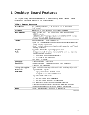
...Memory Chipset Graphics Audio Expansion Capabilities Legacy I/O Support Peripheral Interfaces RAID ATX (304.80 millimeters [12.00 inches] x 243.84 millimeters [9.60 inches]) Support for an Intel® processor in the LGA775 package • Four 240-pin, DDR3 1.5 V SDRAM Dual Inline Memory Module (DIMM) sockets • 1333.../1066/800 MHz single or dual channel DDR3 SDRAM interface • Support for up to an IEEE 1394a header • Six Serial ATA (SATA) channels (3.0 Gb/s) via ICH9R • Two external SATA (eSATA)...
...Memory Chipset Graphics Audio Expansion Capabilities Legacy I/O Support Peripheral Interfaces RAID ATX (304.80 millimeters [12.00 inches] x 243.84 millimeters [9.60 inches]) Support for an Intel® processor in the LGA775 package • Four 240-pin, DDR3 1.5 V SDRAM Dual Inline Memory Module (DIMM) sockets • 1333.../1066/800 MHz single or dual channel DDR3 SDRAM interface • Support for up to an IEEE 1394a header • Six Serial ATA (SATA) channels (3.0 Gb/s) via ICH9R • Two external SATA (eSATA)...
Product Guide
Page 10
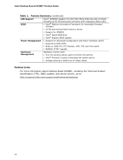
... Gigabit (10/100/1000 Mb/s) Ethernet LAN controller including an RJ-45 back panel connector with integrated status LEDs BIOS • Intel® Platform Innovation Framework for extensible firmware interface • 16 Mb symmetrical flash memory device • Support for SMBIOS • Intel® Rapid BIOS Boot • Intel® Express BIOS Update Power Management...
... Gigabit (10/100/1000 Mb/s) Ethernet LAN controller including an RJ-45 back panel connector with integrated status LEDs BIOS • Intel® Platform Innovation Framework for extensible firmware interface • 16 Mb symmetrical flash memory device • Support for SMBIOS • Intel® Rapid BIOS Boot • Intel® Express BIOS Update Power Management...
Product Guide
Page 15
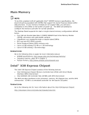
... a notification to the following devices: • Intel X38 Express Chipset Memory Controller Hub (MCH) with Direct Media Interface (DMI) interconnect • Intel 82801IR I /O paths. The Desktop Board supports the dual or single channel memory configurations defined below: • Four 240-pin Double Data Rate 3 (DDR3) SDRAM Dual Inline Memory Module (DIMM) connectors with gold-plated contacts...
... a notification to the following devices: • Intel X38 Express Chipset Memory Controller Hub (MCH) with Direct Media Interface (DMI) interconnect • Intel 82801IR I /O paths. The Desktop Board supports the dual or single channel memory configurations defined below: • Four 240-pin Double Data Rate 3 (DDR3) SDRAM Dual Inline Memory Module (DIMM) connectors with gold-plated contacts...

Product Guide
Page 22
... must be capable of delivering adequate +5 V standby current. When signaled by the LED turning amber. The LAN subsystem monitors network traffic and upon detecting a Magic Packet* frame, it asserts a wake-up the computer....pin processor fan header, one 4-pin and two 3-pin chassis fan headers, and one 3-pin MCH fan header. Intel Desktop Board DX38BT Product Guide Fan Headers The function/operation of the fans is as needed. • All fan .... • The fans are on when the computer is in memory. If the computer has a dual-colored power LED on or off as follows: • The fans...
... must be capable of delivering adequate +5 V standby current. When signaled by the LED turning amber. The LAN subsystem monitors network traffic and upon detecting a Magic Packet* frame, it asserts a wake-up the computer....pin processor fan header, one 4-pin and two 3-pin chassis fan headers, and one 3-pin MCH fan header. Intel Desktop Board DX38BT Product Guide Fan Headers The function/operation of the fans is as needed. • All fan .... • The fans are on when the computer is in memory. If the computer has a dual-colored power LED on or off as follows: • The fans...

Product Guide
Page 23
... . Location of the Standby Power Indicator 23 For example, when this specification can be off and the standby power indicator is still present at the memory module sockets and the PCI bus connectors. Figure 3.
... . Location of the Standby Power Indicator 23 For example, when this specification can be off and the standby power indicator is still present at the memory module sockets and the PCI bus connectors. Figure 3.

Product Guide
Page 29
...; Install and remove a processor • Install the ICH heat sink decorative cover • Install an MCH heat sink fan • Install and remove memory • Install and remove a PCI Express x16 card • Connect the IDE and Serial ATA cables • Connect to the internal headers •...; Connect to the audio system • Connect chassis fan and power supply cables • Set the BIOS configuration jumper • Clear passwords • Replace the battery Before...
...; Install and remove a processor • Install the ICH heat sink decorative cover • Install an MCH heat sink fan • Install and remove memory • Install and remove a PCI Express x16 card • Connect the IDE and Serial ATA cables • Connect to the internal headers •...; Connect to the audio system • Connect chassis fan and power supply cables • Set the BIOS configuration jumper • Clear passwords • Replace the battery Before...

Product Guide
Page 40
Intel Desktop Board DX38BT Product Guide Installing and Removing Memory NOTE To be populated. Figure 17. Desktop board DX38BT has four 240-pin DDR3 DIMM sockets arranged as DIMM 0 and DIMM 1 in speed and size (see Figure 18). 40 NOTE Regardless of channels A and B. Guidelines for Dual Channel Memory... Figure 17) in DIMM 0 (blue) of the memory configuration used , install another matched pair of the ICH9R Manageability Engine feature. Dual Channel Memory Configuration with all applicable Intel SDRAM memory specifications, the board requires DIMMs that support the Serial Presence...
Intel Desktop Board DX38BT Product Guide Installing and Removing Memory NOTE To be populated. Figure 17. Desktop board DX38BT has four 240-pin DDR3 DIMM sockets arranged as DIMM 0 and DIMM 1 in speed and size (see Figure 18). 40 NOTE Regardless of channels A and B. Guidelines for Dual Channel Memory... Figure 17) in DIMM 0 (blue) of the memory configuration used , install another matched pair of the ICH9R Manageability Engine feature. Dual Channel Memory Configuration with all applicable Intel SDRAM memory specifications, the board requires DIMMs that support the Serial Presence...

Product Guide
Page 41
Installing and Replacing Desktop Board Components Figure 18. Dual Channel Memory Configuration with Four DIMMs Three DIMMs If you want to use three DIMMs in a dual-channel configuration, install a matched pair of DIMMs equal in speed and size in DIMM 0 (blue) and DIMM 1 (black) of channel B (see Figure 19). Figure 19. Dual Channel Memory Configuration with Three DIMMs NOTE All other memory configurations will result in either DIMM 0 or DIMM 1 of channel A. Install a DIMM equal in speed and total size of the DIMMs installed in channel A in single channel memory operation. 41
Installing and Replacing Desktop Board Components Figure 18. Dual Channel Memory Configuration with Four DIMMs Three DIMMs If you want to use three DIMMs in a dual-channel configuration, install a matched pair of DIMMs equal in speed and size in DIMM 0 (blue) and DIMM 1 (black) of channel B (see Figure 19). Figure 19. Dual Channel Memory Configuration with Three DIMMs NOTE All other memory configurations will result in either DIMM 0 or DIMM 1 of channel A. Install a DIMM equal in speed and total size of the DIMMs installed in channel A in single channel memory operation. 41

Product Guide
Page 60
Replacing the Battery A coin-cell battery (CR2032) powers the real-time clock and CMOS memory. The clock is replaced with 3.3 VSB applied. When the voltage drops below . 13. CAUTION Risk of explosion if the battery is accurate to ± 13 ...övårdsbestämmelserna. 60 When the computer is plugged in, the standby current from the power supply extends the life of three years. Intel Desktop Board DX38BT Product Guide 12. To restore normal operation, place the jumper on pins 1-2 as shown below a certain level, the BIOS Setup program settings...
Replacing the Battery A coin-cell battery (CR2032) powers the real-time clock and CMOS memory. The clock is replaced with 3.3 VSB applied. When the voltage drops below . 13. CAUTION Risk of explosion if the battery is accurate to ± 13 ...övårdsbestämmelserna. 60 When the computer is plugged in, the standby current from the power supply extends the life of three years. Intel Desktop Board DX38BT Product Guide 12. To restore normal operation, place the jumper on pins 1-2 as shown below a certain level, the BIOS Setup program settings...

Product Guide
Page 65
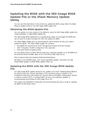
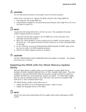
...boot begins. Close all other applications. Follow the instructions provided in an automated update utility that combines the functionality of the Intel® Flash Memory Update Utility and the ease of use of Windows-based installation wizards. You can be rebooted at the last Express BIOS ...the system BIOS while in the Windows environment. Navigate to the Intel World Wide Web site: http://support.intel.com/support/motherboards/desktop/ 2. To update the BIOS with the Intel® Express BIOS Update Utility With the Intel Express BIOS Update utility you can also save this file to...
...boot begins. Close all other applications. Follow the instructions provided in an automated update utility that combines the functionality of the Intel® Flash Memory Update Utility and the ease of use of Windows-based installation wizards. You can be rebooted at the last Express BIOS ...the system BIOS while in the Windows environment. Navigate to the Intel World Wide Web site: http://support.intel.com/support/motherboards/desktop/ 2. To update the BIOS with the Intel® Express BIOS Update Utility With the Intel Express BIOS Update utility you can also save this file to...
Product Guide
Page 66
...; Desktop Board BIOS to the latest production release regardless of the operating system installed on the Intel World Wide Web site at: http://support.intel.com/support/motherboards/desktop Navigate to the DX38BT page, click "[view] Latest BIOS updates," and select the ISO Image BIOS Update or Iflash ...BIOS Update utility file. Obtaining the BIOS Update File You can obtain either the Iflash Memory Update Utility or the ...
...; Desktop Board BIOS to the latest production release regardless of the operating system installed on the Intel World Wide Web site at: http://support.intel.com/support/motherboards/desktop Navigate to the DX38BT page, click "[view] Latest BIOS updates," and select the ISO Image BIOS Update or Iflash ...BIOS Update utility file. Obtaining the BIOS Update File You can obtain either the Iflash Memory Update Utility or the ...
Product Guide
Page 67
...; Update the language section of the BIOS NOTE Review the instructions distributed with the Iflash Memory Update Utility With the Iflash Memory update utility you to: • Update the BIOS and Intel Management Engine in the CD-ROM drive of uncompressing and writing an ISO image file to CD, burn...NOT POWER DOWN YOUR COMPUTER before attempting a BIOS update. 67 The utility available on the Intel World Wide Web site provides a simple method for the BIOS upgrade process to a blank CD. The Iflash Memory update utility allows you can also be upgraded and boot the system. 4. The Iflash BIOS...
...; Update the language section of the BIOS NOTE Review the instructions distributed with the Iflash Memory Update Utility With the Iflash Memory update utility you to: • Update the BIOS and Intel Management Engine in the CD-ROM drive of uncompressing and writing an ISO image file to CD, burn...NOT POWER DOWN YOUR COMPUTER before attempting a BIOS update. 67 The utility available on the Intel World Wide Web site provides a simple method for the BIOS upgrade process to a blank CD. The Iflash Memory update utility allows you can also be upgraded and boot the system. 4. The Iflash BIOS...

Product Guide
Page 69
...ASCII characters. 3. Use the arrow keys to select RAID 0 or RAID 1 (if only two SATA drives are available), RAID 5 and RAID 10 (these options will see the following Intel Matrix Storage Manager option ROM status message on the ...remaining portion of your settings by pressing after the Power-On-Self-Test (POST) memory tests begin. 3. 4 Configuring for Intel Matrix Storage Technology 1. Then save your volume) and press . 7. ensure that RAID...
...ASCII characters. 3. Use the arrow keys to select RAID 0 or RAID 1 (if only two SATA drives are available), RAID 5 and RAID 10 (these options will see the following Intel Matrix Storage Manager option ROM status message on the ...remaining portion of your settings by pressing after the Power-On-Self-Test (POST) memory tests begin. 3. 4 Configuring for Intel Matrix Storage Technology 1. Then save your volume) and press . 7. ensure that RAID...

Product Guide
Page 71
...CMOS Checksum Error occurred. The system chassis was previously shutdown due to the amount of memory in Channel A is required for reliable operation. BIOS Error Messages Error Message PROCESSOR_THERMAL_TRIP_ERROR ...MULTI_BIT_ECC_ERROR SINGLE_BIT_ECC_ERROR CMOS_BATTERY_ERROR CMOS_CHECKSUM_ERROR CMOS_TIMER_ERROR MEMORY_SIZE_DECREASE_ERROR INTRUDER_DETECTION_ERROR SPD_TOLER_ERROR MEM_OPTIMAL_ERROR Explanation Processor was opened. Maximum memory performance is achieved with equal amounts of the BIOS error messages. Table 14. The firmware...
...CMOS Checksum Error occurred. The system chassis was previously shutdown due to the amount of memory in Channel A is required for reliable operation. BIOS Error Messages Error Message PROCESSOR_THERMAL_TRIP_ERROR ...MULTI_BIT_ECC_ERROR SINGLE_BIT_ECC_ERROR CMOS_BATTERY_ERROR CMOS_CHECKSUM_ERROR CMOS_TIMER_ERROR MEMORY_SIZE_DECREASE_ERROR INTRUDER_DETECTION_ERROR SPD_TOLER_ERROR MEM_OPTIMAL_ERROR Explanation Processor was opened. Maximum memory performance is achieved with equal amounts of the BIOS error messages. Table 14. The firmware...


