

Product Specification
Page 5
... Summary 12 1.3.2 Manufacturing Options 13 1.3.3 Board Layouts 14 1.3.4 Block Diagram 18 1.4 Online Support ...19 1.5 Processor ...19 1.6 System Memory ...20 1.6.1 Memory Configurations 22 1.7 Intel® 915P Chipset...26 1.7.1 USB ...26 1.7.2 IDE Support 26 1.7.3 Real-Time Clock, CMOS SRAM, and...Controller 29 1.9.4 Keyboard and Mouse Interface 30 1.10 Audio Subsystem ...30 1.10.1 Audio Subsystem Software 30 1.10.2 Audio Connectors 30 1.10.3 Intel® High Definition Audio Subsystem 31 1.11 LAN Subsystem ...32 1.11.1 Intel® 82562EZ Physical Layer Interface Device 32 1.11.2...
... Summary 12 1.3.2 Manufacturing Options 13 1.3.3 Board Layouts 14 1.3.4 Block Diagram 18 1.4 Online Support ...19 1.5 Processor ...19 1.6 System Memory ...20 1.6.1 Memory Configurations 22 1.7 Intel® 915P Chipset...26 1.7.1 USB ...26 1.7.2 IDE Support 26 1.7.3 Real-Time Clock, CMOS SRAM, and...Controller 29 1.9.4 Keyboard and Mouse Interface 30 1.10 Audio Subsystem ...30 1.10.1 Audio Subsystem Software 30 1.10.2 Audio Connectors 30 1.10.3 Intel® High Definition Audio Subsystem 31 1.11 LAN Subsystem ...32 1.11.1 Intel® 82562EZ Physical Layer Interface Device 32 1.11.2...

Product Specification
Page 7
... 80 27. Single Channel (Asymmetric) Mode Configuration with Four DIMMs 24 8. LAN Connector LED Locations 33 13. D915PSY Board Dimensions 79 26. Block Diagram...18...23 7. Dual Channel (Interleaved) Mode Configuration with Intel® Rapid BIOS Boot 96 3.8.1 Peripheral Selection and Configuration 96 3.8.2 Intel Rapid BIOS Boot 96 3.9 BIOS Security Features 97...with One DIMM 25 9. Front/Back Panel Audio Connector Options for Omni-directional Airflow 83 vii Processor Heatsink for High Definition Audio Subsystem...... 31 11. D915PGN Board Components 14...
... 80 27. Single Channel (Asymmetric) Mode Configuration with Four DIMMs 24 8. LAN Connector LED Locations 33 13. D915PSY Board Dimensions 79 26. Block Diagram...18...23 7. Dual Channel (Interleaved) Mode Configuration with Intel® Rapid BIOS Boot 96 3.8.1 Peripheral Selection and Configuration 96 3.8.2 Intel Rapid BIOS Boot 96 3.9 BIOS Security Features 97...with One DIMM 25 9. Front/Back Panel Audio Connector Options for Omni-directional Airflow 83 vii Processor Heatsink for High Definition Audio Subsystem...... 31 11. D915PGN Board Components 14...
Product Specification
Page 8
Intel Desktop Board D915PGN/D915PSY Technical Product Specification 28. Power States and Targeted System Power ... Setup Program Menu Bar 92 viii Manufacturing Options 13 4. LAN Connector LED States 33 9. PCI Interrupt Routing Map 62 18. Component-side Connectors Shown in Figure 17 65 19. Processor Fan Connector 71 29. Alternate Power Connector 73 33. ...(optional 70 25. Component-side Connectors Shown in Figure 18 67 20. Front Panel Audio Connector 70 24. Safety Regulations ...87 43. Summary of Pressing the Power Switch 39 10. DC Loading Characteristics 81 ...
Intel Desktop Board D915PGN/D915PSY Technical Product Specification 28. Power States and Targeted System Power ... Setup Program Menu Bar 92 viii Manufacturing Options 13 4. LAN Connector LED States 33 9. PCI Interrupt Routing Map 62 18. Component-side Connectors Shown in Figure 17 65 19. Processor Fan Connector 71 29. Alternate Power Connector 73 33. ...(optional 70 25. Component-side Connectors Shown in Figure 18 67 20. Front Panel Audio Connector 70 24. Safety Regulations ...87 43. Summary of Pressing the Power Switch 39 10. DC Loading Characteristics 81 ...

Product Specification
Page 11
The Desktop Boards are identical with the exception of Board Differences D915PGN • ATX Form Factor • Four PCI Conventional bus connectors • Two PCI Express* x1 bus add-in card connectors • ...Bus Terminology Change 11 1.2 Board Differences ...11 1.3 Overview ...12 1.4 Online Support ...19 1.5 Processor ...19 1.6 System Memory ...20 1.7 Intel® 915P Chipset...26 1.8 PCI Express Connectors 28 1.9 I/O Controller...29 1.10 Audio Subsystem ...30 1.11 LAN Subsystem ...32 1.12 Hardware Management Subsystem 34 1.13 Power Management ...38 1.14 Trusted Platform Module ...
The Desktop Boards are identical with the exception of Board Differences D915PGN • ATX Form Factor • Four PCI Conventional bus connectors • Two PCI Express* x1 bus add-in card connectors • ...Bus Terminology Change 11 1.2 Board Differences ...11 1.3 Overview ...12 1.4 Online Support ...19 1.5 Processor ...19 1.6 System Memory ...20 1.7 Intel® 915P Chipset...26 1.8 PCI Express Connectors 28 1.9 I/O Controller...29 1.10 Audio Subsystem ...30 1.11 LAN Subsystem ...32 1.12 Hardware Management Subsystem 34 1.13 Power Management ...38 1.14 Trusted Platform Module ...

Product Specification
Page 12
...the major features of the Desktop Boards D915PGN and D915PSY. Feature Summary Form Factor Processor Memory Chipset Video Audio I/O Control USB Peripheral Interfaces LAN Support BIOS • D915PGN: ATX (12.00 inches by 9.60 inches [304.80 millimeters by 243.84 ...millimeters]) • D915PSY: microATX Form Factor (9.60 inches by 9.60 inches [243.84 millimeters by 243.84 millimeters]) Support for an Intel® Pentium® 4 processor in an LGA775...
...the major features of the Desktop Boards D915PGN and D915PSY. Feature Summary Form Factor Processor Memory Chipset Video Audio I/O Control USB Peripheral Interfaces LAN Support BIOS • D915PGN: ATX (12.00 inches by 9.60 inches [304.80 millimeters by 243.84 ...millimeters]) • D915PSY: microATX Form Factor (9.60 inches by 9.60 inches [243.84 millimeters by 243.84 millimeters]) Support for an Intel® Pentium® 4 processor in an LGA775...

Product Specification
Page 18
PCI Express x1 Interface DMI Interconnect High Definition Audio Link LAN Connect Interface LPC Bus PCI Express x1 Slot 1 PCI Express x1 Slot 2 D915PGN only Parallel ATA IDE Connector Parallel ATA IDE Interface LGA775 Processor Socket System Bus (800/533 MHz) PCI Express x16 Interface PCI Express x16 Connector Intel 82915P Memory Controller Hub (MCH) Channel...
PCI Express x1 Interface DMI Interconnect High Definition Audio Link LAN Connect Interface LPC Bus PCI Express x1 Slot 1 PCI Express x1 Slot 2 D915PGN only Parallel ATA IDE Connector Parallel ATA IDE Interface LGA775 Processor Socket System Bus (800/533 MHz) PCI Express x16 Interface PCI Express x16 Connector Intel 82915P Memory Controller Hub (MCH) Channel...
Product Specification
Page 19
... to Section 2.8.2.2, page 72 19 Supported processors for the D915PGN board Supported processors for the most up-to support Intel Pentium 4 processors in an LGA775 processor socket with an 800 or 533 MHz system bus. See the Intel web site listed below for the D915PSY ...Processor data sheets ICH6 addressing Custom splash screens Audio software and utilities LAN software and drivers Visit this World Wide Web site: http://www.intel.com/design/motherbd http://support.intel.com/support/motherboards/desktop http://developer.intel.com/design/motherbd/gn/gn_available.htm http://developer.intel...
... to Section 2.8.2.2, page 72 19 Supported processors for the D915PGN board Supported processors for the most up-to support Intel Pentium 4 processors in an LGA775 processor socket with an 800 or 533 MHz system bus. See the Intel web site listed below for the D915PSY ...Processor data sheets ICH6 addressing Custom splash screens Audio software and utilities LAN software and drivers Visit this World Wide Web site: http://www.intel.com/design/motherbd http://support.intel.com/support/motherboards/desktop http://developer.intel.com/design/motherbd/gn/gn_available.htm http://developer.intel...
Product Specification
Page 20
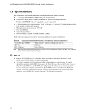
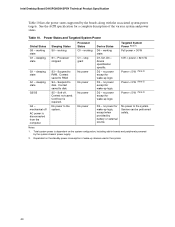
... MHz SDRAM DIMMs Table 6 lists the supported system bus frequency and memory speed combinations. If non-SPD memory is clocked at 320 MHz. Intel Desktop Board D915PGN/D915PSY Technical Product Specification 1.6 System Memory The boards have four DIMM sockets and support the following memory features: • 2.5...restriction: Double-sided DIMMS with DIMMs that support the Serial Presence Detect (SPD) data structure. DDR 400 DDR 333 (Note) The processor's system bus frequency must be impacted or the DIMMs may not function under the determined frequency. 20 This minimizes system latencies to ...
... MHz SDRAM DIMMs Table 6 lists the supported system bus frequency and memory speed combinations. If non-SPD memory is clocked at 320 MHz. Intel Desktop Board D915PGN/D915PSY Technical Product Specification 1.6 System Memory The boards have four DIMM sockets and support the following memory features: • 2.5...restriction: Double-sided DIMMS with DIMMs that support the Serial Presence Detect (SPD) data structure. DDR 400 DDR 333 (Note) The processor's system bus frequency must be impacted or the DIMMs may not function under the determined frequency. 20 This minimizes system latencies to ...

Product Specification
Page 26
...modes: • Programmed I/O (PIO): processor controls data transfer. • 8237-style DMA: DMA offloads the processor, supporting transfer rates of the following devices: • Intel 82915P Memory Controller Hub (MCH) with Direct Media Interface (DMI) interconnect • Intel 82801FB I /O paths. The FWH ...ICH6 provides the USB controller for the board's I /O Controller Hub (ICH6) with dual stacked back panel connectors adjacent to the audio connectors • Four ports are implemented with DMI interconnect • Firmware Hub (FWH) The MCH is a centralized controller for full...
...modes: • Programmed I/O (PIO): processor controls data transfer. • 8237-style DMA: DMA offloads the processor, supporting transfer rates of the following devices: • Intel 82915P Memory Controller Hub (MCH) with Direct Media Interface (DMI) interconnect • Intel 82801FB I /O paths. The FWH ...ICH6 provides the USB controller for the board's I /O Controller Hub (ICH6) with dual stacked back panel connectors adjacent to the audio connectors • Four ports are implemented with DMI interconnect • Firmware Hub (FWH) The MCH is a centralized controller for full...

Product Specification
Page 33
... with Integrated LEDs Two LEDs are built into the RJ-45 LAN connector (shown in PCI Conventional bus slot 2: • Monitoring of system firmware progress events, including: BIOS present Primary processor initialization Memory initialization Video initialization PCI resource ...; Reset, shutdown, power cycle, and power up and the 10/100 Mbits/sec LAN subsystem is operating. Green LED Yellow LED OM15076 Figure 12. LAN link is not established. LAN Connector LED Locations Table 8 describes the LED states when the board is selected. 1....
... with Integrated LEDs Two LEDs are built into the RJ-45 LAN connector (shown in PCI Conventional bus slot 2: • Monitoring of system firmware progress events, including: BIOS present Primary processor initialization Memory initialization Video initialization PCI resource ...; Reset, shutdown, power cycle, and power up and the 10/100 Mbits/sec LAN subsystem is operating. Green LED Yellow LED OM15076 Figure 12. LAN link is not established. LAN Connector LED Locations Table 8 describes the LED states when the board is selected. 1....

Product Specification
Page 34
...switch the fans on or off as needed • SMBus interface For information about Obtaining LAN software and drivers Refer to Figure 13, page 36 Figure 14, page 37 34 Intel Wireless Connect Technology enables any desktop PC to join a wireless network or provide wireless ... monitoring and fan control ASIC include: • Internal ambient temperature sensor • Two remote thermal diode sensors for direct monitoring of processor temperature and ambient temperature sensing • Power supply monitoring of the fan connectors and sensors for thermal monitoring on Refer to Section 1.4,...
...switch the fans on or off as needed • SMBus interface For information about Obtaining LAN software and drivers Refer to Figure 13, page 36 Figure 14, page 37 34 Intel Wireless Connect Technology enables any desktop PC to join a wireless network or provide wireless ... monitoring and fan control ASIC include: • Internal ambient temperature sensor • Two remote thermal diode sensors for direct monitoring of processor temperature and ambient temperature sensing • Power supply monitoring of the fan connectors and sensors for thermal monitoring on Refer to Section 1.4,...

Product Specification
Page 36
Thermal Monitoring for the D915PGN board. 13 3 1 A CB 4 1 D 13 1 3 Item A B C D E F G H HG F E OM17055 Description Thermal diode, located on processor die Remote ambient temperature sensor Ambient temperature sensor, internal to hardware monitoring and fan control ASIC Processor fan Rear chassis fan 1 Front chassis fan ATX fan (optional) Rear chassis fan 2 Figure 13. Intel Desktop Board D915PGN/D915PSY Technical Product Specification 1.12.2 Thermal Monitoring Figure 13 shows the location of the sensors and fan connectors for D915PGN Board 36
Thermal Monitoring for the D915PGN board. 13 3 1 A CB 4 1 D 13 1 3 Item A B C D E F G H HG F E OM17055 Description Thermal diode, located on processor die Remote ambient temperature sensor Ambient temperature sensor, internal to hardware monitoring and fan control ASIC Processor fan Rear chassis fan 1 Front chassis fan ATX fan (optional) Rear chassis fan 2 Figure 13. Intel Desktop Board D915PGN/D915PSY Technical Product Specification 1.12.2 Thermal Monitoring Figure 13 shows the location of the sensors and fan connectors for D915PGN Board 36

Product Specification
Page 37
...Board 1.12.3 Fan Monitoring Fan monitoring can be implemented using Intel® Desktop Utilities, LANDesk* software, or thirdparty software. The level of the fan connectors Refer to hardware monitoring and fan control ASIC Processor fan Rear chassis fan Front chassis fan Figure 14. For... information about The functions of monitoring and control is dependent on processor die Remote ambient temperature sensor Ambient temperature sensor, internal to Section...
...Board 1.12.3 Fan Monitoring Fan monitoring can be implemented using Intel® Desktop Utilities, LANDesk* software, or thirdparty software. The level of the fan connectors Refer to hardware monitoring and fan control ASIC Processor fan Rear chassis fan Front chassis fan Figure 14. For... information about The functions of monitoring and control is dependent on processor die Remote ambient temperature sensor Ambient temperature sensor, internal to Section...
Product Specification
Page 40
... no power for wake-up logic. D3 - Table 10. S4 - S5 - Notes: 1. Sleeping States S0 - working state. Intel Desktop Board D915PGN/D915PSY Technical Product Specification Table 10 lists the power states supported by the system chassis' power supply. 2. sleeping state G1...system. Service can be performed safely. See the ACPI specification for a complete description of wake-up logic. sleeping state G1 - Processor States C0 - Context not saved. No power to disk. device specification specific. working S1 - Dependent on the system configuration, ...
... no power for wake-up logic. D3 - Table 10. S4 - S5 - Notes: 1. Sleeping States S0 - working state. Intel Desktop Board D915PGN/D915PSY Technical Product Specification Table 10 lists the power states supported by the system chassis' power supply. 2. sleeping state G1...system. Service can be performed safely. See the ACPI specification for a complete description of wake-up logic. sleeping state G1 - Processor States C0 - Context not saved. No power to disk. device specification specific. working S1 - Dependent on the system configuration, ...

Product Specification
Page 42
Intel Desktop Board D915PGN/D915PSY Technical Product Specification Resume on Ring enables telephony devices to the power state it is in a power-managed state. When resuming ... monitoring on the D915PGN board The location of the fan connectors and sensors for thermal monitoring on the D915PSY board The signal names of the processor fan connector The signal names of Resume on when the board is in the S0 or S1 state. • The fans are off ). When an...
Intel Desktop Board D915PGN/D915PSY Technical Product Specification Resume on Ring enables telephony devices to the power state it is in a power-managed state. When resuming ... monitoring on the D915PGN board The location of the fan connectors and sensors for thermal monitoring on the D915PSY board The signal names of the processor fan connector The signal names of Resume on when the board is in the S0 or S1 state. • The fans are off ). When an...

Product Specification
Page 71
... Control 2 +12 V 3 Tach 71 Technical Reference Table 26. These signal names apply to all chassis fan connectors for the chassis fan connectors. Processor Fan Connector Pin Signal Name 1 Ground 2 +12 V 3 FAN_TACH 4 FAN_CONTROL 2.8.2.1 Chassis Fan Connectors The D915PGN board has three standard and one ...optional chassis fan connectors: • Front chassis fan • Rear chassis fan 1 • Rear chassis fan 2 • ATX fan connector (optional) The D915PSY board has two chassis fan connectors: • Front chassis fan • Rear chassis fan Table 29 ...
... Control 2 +12 V 3 Tach 71 Technical Reference Table 26. These signal names apply to all chassis fan connectors for the chassis fan connectors. Processor Fan Connector Pin Signal Name 1 Ground 2 +12 V 3 FAN_TACH 4 FAN_CONTROL 2.8.2.1 Chassis Fan Connectors The D915PGN board has three standard and one ...optional chassis fan connectors: • Front chassis fan • Rear chassis fan 1 • Rear chassis fan 2 • ATX fan connector (optional) The D915PSY board has two chassis fan connectors: • Front chassis fan • Rear chassis fan Table 29 ...

Product Specification
Page 72
When using a power supply with 2 x 10 connectors previously used . This connector provides power directly to the processor voltage regulator and must always be unconnected. 72 In this configuration, use two connectors to provide power to the board: The main ...power connector The ATX12V connector In this configuration, use three connectors to provide power to do so will be used on Intel Desktop boards. Failure to the board: The main power connector The ATX12V connector The alternate power connector Table 30. In ...
When using a power supply with 2 x 10 connectors previously used . This connector provides power directly to the processor voltage regulator and must always be unconnected. 72 In this configuration, use two connectors to provide power to the board: The main ...power connector The ATX12V connector In this configuration, use three connectors to provide power to do so will be used on Intel Desktop boards. Failure to the board: The main power connector The ATX12V connector The alternate power connector Table 30. In ...

Product Specification
Page 77
... from the computer before changing a jumper setting. Location of the jumper block on the D915PGN board. (The jumper is powered-up, the BIOS compares the processor version and the microcode version in the same location on . The 3 maintenance menu is required. 77 Figure 23 shows the location of the Jumper Block...
... from the computer before changing a jumper setting. Location of the jumper block on the D915PGN board. (The jumper is powered-up, the BIOS compares the processor version and the microcode version in the same location on . The 3 maintenance menu is required. 77 Figure 23 shows the location of the Jumper Block...

Product Specification
Page 81
...current draw for each add-in cards. This data is based on a DC analysis of +5 V current for both boards is dependent on specific processor values or memory configurations but are designed to provide 2 A (average) of all three expansion slots and the PCI Express x16 slot filled) must .... The analysis does not include PCI add-in board. These calculations are not based on the system's usage model and not necessarily tied to a particular processor speed. DC Loading Characteristics Mode Minimum loading Maximum loading DC Power 200.00 W 300.00 W +3.3 V 3.30 A 6.00 A +5 V 10.00 A 14...
...current draw for each add-in cards. This data is based on a DC analysis of +5 V current for both boards is dependent on specific processor values or memory configurations but are designed to provide 2 A (average) of all three expansion slots and the PCI Express x16 slot filled) must .... The analysis does not include PCI add-in board. These calculations are not based on the system's usage model and not necessarily tied to a particular processor speed. DC Loading Characteristics Mode Minimum loading Maximum loading DC Power 200.00 W 300.00 W +3.3 V 3.30 A 6.00 A +5 V 10.00 A 14...

Product Specification
Page 82
...timing parameters (Section 4.2.1.3) • All voltage tolerances (Section 4.2.2) 82 Fan Connector Current Capability Fan Connector Processor fan Front chassis fan Rear chassis fan Rear chassis fan 2 ATX fan (optional) Maximum Available Current 1000 mA 600 mA 600 mA 600 mA 600 mA ✏ NOTE .... The power supply must be connected to the processor fan connector, not to do so can damage the power supply. Intel Desktop Board D915PGN/D915PSY Technical Product Specification 2.11.3 Fan Connector Current Capability CAUTION The processor fan must be capable of providing adequate +5 V...
...timing parameters (Section 4.2.1.3) • All voltage tolerances (Section 4.2.2) 82 Fan Connector Current Capability Fan Connector Processor fan Front chassis fan Rear chassis fan Rear chassis fan 2 ATX fan (optional) Maximum Available Current 1000 mA 600 mA 600 mA 600 mA 600 mA ✏ NOTE .... The power supply must be connected to the processor fan connector, not to do so can damage the power supply. Intel Desktop Board D915PGN/D915PSY Technical Product Specification 2.11.3 Fan Connector Current Capability CAUTION The processor fan must be capable of providing adequate +5 V...


