

Product Specification
Page 5
...1.1 PCI Bus Terminology Change 11 1.2 Board Differences ...11 1.3 Overview ...12 1.3.1 Feature Summary 12 1.3.2 Manufacturing Options 13 1.3.3 Board Layouts 14 1.3.4 Block Diagram 18 1.4 Online Support ...19 1.5 Processor ...19 1.6 System Memory ...20 1.6.1 Memory Configurations 22 1.7 Intel® 915P Chipset...26 1.7.1 USB ...26 1.7.2 IDE Support 26 1.7.3 Real-Time Clock, CMOS SRAM, and Battery 28 1.8 PCI Express Connectors 28 1.9 I/O Controller...29 1.9.1 Serial Ports ...29 1.9.2 Parallel Port 29 1.9.3 Diskette Drive Controller 29 1.9.4 Keyboard and Mouse Interface 30 1.10 Audio...
...1.1 PCI Bus Terminology Change 11 1.2 Board Differences ...11 1.3 Overview ...12 1.3.1 Feature Summary 12 1.3.2 Manufacturing Options 13 1.3.3 Board Layouts 14 1.3.4 Block Diagram 18 1.4 Online Support ...19 1.5 Processor ...19 1.6 System Memory ...20 1.6.1 Memory Configurations 22 1.7 Intel® 915P Chipset...26 1.7.1 USB ...26 1.7.2 IDE Support 26 1.7.3 Real-Time Clock, CMOS SRAM, and Battery 28 1.8 PCI Express Connectors 28 1.9 I/O Controller...29 1.9.1 Serial Ports ...29 1.9.2 Parallel Port 29 1.9.3 Diskette Drive Controller 29 1.9.4 Keyboard and Mouse Interface 30 1.10 Audio...

Product Specification
Page 7
... Board Dimensions 79 26. Contents 3.6 BIOS Updates ...94 3.6.1 Language Support 94 3.6.2 Custom Splash Screen 94 3.7 Boot Options ...95 3.7.1 CD-ROM Boot 95 3.7.2 Network Boot 95 3.7.3 Booting Without Attached Devices 95 3.7.4 Changing the Default Boot Device During POST 95 3.8 Fast Booting Systems with Three DIMMs 23 7. Dual Channel (Interleaved) Mode Configuration with Intel® Rapid BIOS Boot 96 3.8.1 Peripheral Selection and Configuration 96 3.8.2 Intel Rapid BIOS Boot 96 3.9 BIOS Security Features 97 4 Error Messages and Beep Codes 4.1 BIOS Error Messages 99 4.2 Port...
... Board Dimensions 79 26. Contents 3.6 BIOS Updates ...94 3.6.1 Language Support 94 3.6.2 Custom Splash Screen 94 3.7 Boot Options ...95 3.7.1 CD-ROM Boot 95 3.7.2 Network Boot 95 3.7.3 Booting Without Attached Devices 95 3.7.4 Changing the Default Boot Device During POST 95 3.8 Fast Booting Systems with Three DIMMs 23 7. Dual Channel (Interleaved) Mode Configuration with Intel® Rapid BIOS Boot 96 3.8.1 Peripheral Selection and Configuration 96 3.8.2 Intel Rapid BIOS Boot 96 3.9 BIOS Security Features 97 4 Error Messages and Beep Codes 4.1 BIOS Error Messages 99 4.2 Port...
Product Specification
Page 8
Intel Desktop Board D915PGN/D915PSY Technical Product Specification 28. Supported System Bus Frequency and Memory Speed Combinations 20 7. Effects of Board Differences 11 2. DMA Channels ...57 14. Interrupts ...60 17. Component-side Connectors Shown in Figure 2 17 6. Chassis Intrusion Connector 70 26. Serial ATA Connectors 71 28. Chassis Fan Connectors 71 30. Environmental Specifications 86 42. BIOS Setup Program Menu Bar 92 viii LAN Connector LED States 33 9. SCSI Hard Drive Activity LED Connector (Optional 71 27. Front Panel Connector 74 35....
Intel Desktop Board D915PGN/D915PSY Technical Product Specification 28. Supported System Bus Frequency and Memory Speed Combinations 20 7. Effects of Board Differences 11 2. DMA Channels ...57 14. Interrupts ...60 17. Component-side Connectors Shown in Figure 2 17 6. Chassis Intrusion Connector 70 26. Serial ATA Connectors 71 28. Chassis Fan Connectors 71 30. Environmental Specifications 86 42. BIOS Setup Program Menu Bar 92 viii LAN Connector LED States 33 9. SCSI Hard Drive Activity LED Connector (Optional 71 27. Front Panel Connector 74 35....

Product Specification
Page 11
... Chipset...26 1.8 PCI Express Connectors 28 1.9 I/O Controller...29 1.10 Audio Subsystem ...30 1.11 LAN Subsystem ...32 1.12 Hardware Management Subsystem 34 1.13 Power Management ...38 1.14 Trusted Platform Module (Optional 46 1.1 PCI Bus Terminology Change Previous generations of Intel® Desktop Boards used an add-in card connector referred to as PCI. Summary of Board Differences D915PGN • ATX Form Factor • Four PCI Conventional bus connectors • Two PCI Express* x1 bus add-in card connectors • Three chassis fan connectors...
... Chipset...26 1.8 PCI Express Connectors 28 1.9 I/O Controller...29 1.10 Audio Subsystem ...30 1.11 LAN Subsystem ...32 1.12 Hardware Management Subsystem 34 1.13 Power Management ...38 1.14 Trusted Platform Module (Optional 46 1.1 PCI Bus Terminology Change Previous generations of Intel® Desktop Boards used an add-in card connector referred to as PCI. Summary of Board Differences D915PGN • ATX Form Factor • Four PCI Conventional bus connectors • Two PCI Express* x1 bus add-in card connectors • Three chassis fan connectors...

Product Specification
Page 13
... board. ATX fan connector Additional fan connector for PCI Express Revision 1.0a • Suspend to you. Feature Summary (continued) Instantly Available PC Technology • Support for PCI Local Bus Specification Revision 2.2 • Support for use the same LED as the onboard IDE controller. SCSI Hard Drive Activity LED Connector Allows add-in S/PDIF format. Product Description Table 2. Please contact your Intel representative to determine which manufacturing options are available to RAM support • Wake on PCI, RS-232, front panel...
... board. ATX fan connector Additional fan connector for PCI Express Revision 1.0a • Suspend to you. Feature Summary (continued) Instantly Available PC Technology • Support for PCI Local Bus Specification Revision 2.2 • Support for use the same LED as the onboard IDE controller. SCSI Hard Drive Activity LED Connector Allows add-in S/PDIF format. Product Description Table 2. Please contact your Intel representative to determine which manufacturing options are available to RAM support • Wake on PCI, RS-232, front panel...

Product Specification
Page 18
... 18 PCI Express x1 Interface DMI Interconnect High Definition Audio Link LAN Connect Interface LPC Bus PCI Express x1 Slot 1 PCI Express x1 Slot 2 D915PGN only Parallel ATA IDE Connector Parallel ATA IDE Interface LGA775 Processor Socket System Bus (800/533 MHz) PCI Express x16 Interface PCI Express x16 Connector Intel 82915P Memory Controller Hub (MCH) Channel A DIMMs (2) Channel B DIMMs (2) Dual-Channel Memory Bus SMBus USB Back Panel/Front Panel USB Ports LPC Bus I/O Controller LPC Bus Serial Ports Parallel Port PS/2 Mouse PS/2 Keyboard Diskette Drive Connector Intel...
... 18 PCI Express x1 Interface DMI Interconnect High Definition Audio Link LAN Connect Interface LPC Bus PCI Express x1 Slot 1 PCI Express x1 Slot 2 D915PGN only Parallel ATA IDE Connector Parallel ATA IDE Interface LGA775 Processor Socket System Bus (800/533 MHz) PCI Express x16 Interface PCI Express x16 Connector Intel 82915P Memory Controller Hub (MCH) Channel A DIMMs (2) Channel B DIMMs (2) Dual-Channel Memory Bus SMBus USB Back Panel/Front Panel USB Ports LPC Bus I/O Controller LPC Bus Serial Ports Parallel Port PS/2 Mouse PS/2 Keyboard Diskette Drive Connector Intel...

Product Specification
Page 28
... a 1 x 2-pin connector that allows an add-in hard drive controller to 500 MBytes/sec The PCI Express interface supports the PCI Conventional bus configuration mechanism so that the underlying PCI Express architecture is compatible with PCI Conventional compliant operating systems. Additional features of the PCI Express interface includes the following PCI Express connectors: • One PCI Express x16 connector supporting simultaneous transfer speeds up to use the same LED as the onboard IDE controller. When the computer is not plugged into CMOS RAM...
... a 1 x 2-pin connector that allows an add-in hard drive controller to 500 MBytes/sec The PCI Express interface supports the PCI Conventional bus configuration mechanism so that the underlying PCI Express architecture is compatible with PCI Conventional compliant operating systems. Additional features of the PCI Express interface includes the following PCI Express connectors: • One PCI Express x16 connector supporting simultaneous transfer speeds up to use the same LED as the onboard IDE controller. When the computer is not plugged into CMOS RAM...

Product Specification
Page 34
... management features enable the Desktop Boards to be compatible with the Wired for thermal monitoring on the D915PGN board The location of the fan connectors and sensors for Management (WfM) specification. Intel Wireless Connect Technology enables any desktop PC to join a wireless network or provide wireless Access Point services to a home or small office network through the hardware monitoring and fan control ASIC) • Thermal and voltage monitoring • Chassis intrusion detection 1.12.1 Hardware Monitoring and Fan Control ASIC...
... management features enable the Desktop Boards to be compatible with the Wired for thermal monitoring on the D915PGN board The location of the fan connectors and sensors for Management (WfM) specification. Intel Wireless Connect Technology enables any desktop PC to join a wireless network or provide wireless Access Point services to a home or small office network through the hardware monitoring and fan control ASIC) • Thermal and voltage monitoring • Chassis intrusion detection 1.12.1 Hardware Monitoring and Fan Control ASIC...

Product Specification
Page 50
... Recovery Token Security Password (created with the same model as the failed board. 2. Start the Infineon Security Platform Initialization Wizard and check the "I want to the new hard drive - Follow the instructions and create and document the locations for both the archive and restoration key files. This recovery procedure may restore the migratable keys from the previously created Recovery Archives. 1. Intel Desktop Board D915PGN/D915PSY Technical Product Specification...
... Recovery Token Security Password (created with the same model as the failed board. 2. Start the Infineon Security Platform Initialization Wizard and check the "I want to the new hard drive - Follow the instructions and create and document the locations for both the archive and restoration key files. This recovery procedure may restore the migratable keys from the previously created Recovery Archives. 1. Intel Desktop Board D915PGN/D915PSY Technical Product Specification...

Product Specification
Page 51
... ANY PROGRAM UTILIZING THE TPM WILL BECOME INACCESSIBLE IF TPM OWNERSHIP IS CLEARED. Press the key to operate even though the front panel power switch is disabled by the Key Transfer Manager. 11. Start User Initialization Wizard. Provide all the necessary passwords, files, and file locations as requested. The TPM may take up to 20 minutes for detailed instructions). Move the configuration jumper on the Key Transfer Manager...
... ANY PROGRAM UTILIZING THE TPM WILL BECOME INACCESSIBLE IF TPM OWNERSHIP IS CLEARED. Press the key to operate even though the front panel power switch is disabled by the Key Transfer Manager. 11. Start User Initialization Wizard. Provide all the necessary passwords, files, and file locations as requested. The TPM may take up to 20 minutes for detailed instructions). Move the configuration jumper on the Key Transfer Manager...

Product Specification
Page 56
Intel Desktop Board D915PGN/D915PSY Technical Product Specification The amount of the system memory map. Figure 16 shows a schematic of installed memory that can be used when there is no overlap of system addresses. 4 GB Top of System Address Space FLASH APIC Reserved ~20 MB PCI Memory Range contains PCI, chipsets, Direct Media Interface (DMI), and ICH ranges (approximately 750 MB) DRAM Range DOS Compatibility Memory Top of...
Intel Desktop Board D915PGN/D915PSY Technical Product Specification The amount of the system memory map. Figure 16 shows a schematic of installed memory that can be used when there is no overlap of system addresses. 4 GB Top of System Address Space FLASH APIC Reserved ~20 MB PCI Memory Range contains PCI, chipsets, Direct Media Interface (DMI), and ICH ranges (approximately 750 MB) DRAM Range DOS Compatibility Memory Top of...

Product Specification
Page 59
... 01 02 Description Memory controller of Intel 82915P component PCI Express x16 graphics port (Note 1) Integrated graphics controller Integrated graphics controller Intel High Definition Audio Controller PCI Express port 1 (PCI Express x1 bus connector 1) PCI Express port 2 PCI Express port 3 (PCI Express x1 bus connector 2) (Note 2) 00 1C 03 PCI Express port 4 (not used . 59 Technical Reference 2.5 PCI Configuration Space Map Table 15. Not present on add-in cards used ) 00 1D 00 USB UHCI controller 1 00 1D 01 USB UHCI controller 2 00 1D 02 USB UHCI controller 3 00 1D...
... 01 02 Description Memory controller of Intel 82915P component PCI Express x16 graphics port (Note 1) Integrated graphics controller Integrated graphics controller Intel High Definition Audio Controller PCI Express port 1 (PCI Express x1 bus connector 1) PCI Express port 2 PCI Express port 3 (PCI Express x1 bus connector 2) (Note 2) 00 1C 03 PCI Express port 4 (not used . 59 Technical Reference 2.5 PCI Configuration Space Map Table 15. Not present on add-in cards used ) 00 1D 00 USB UHCI controller 1 00 1D 01 USB UHCI controller 2 00 1D 02 USB UHCI controller 3 00 1D...

Product Specification
Page 91
... be updated using a disk-based program. The BIOS Setup program can be used to view and change the BIOS settings for the computer. 3 Overview of BIOS and a revision code. Maintenance Main Advanced Security Power Boot Exit ✏ NOTE The maintenance menu is displayed only when the Desktop Board is poweredup, the BIOS compares the CPU version and the microcode version in configure mode. The FWH contains the BIOS Setup program, POST, the PCI autoconfiguration utility, and Plug and Play support. The...
... be updated using a disk-based program. The BIOS Setup program can be used to view and change the BIOS settings for the computer. 3 Overview of BIOS and a revision code. Maintenance Main Advanced Security Power Boot Exit ✏ NOTE The maintenance menu is displayed only when the Desktop Board is poweredup, the BIOS compares the CPU version and the microcode version in configure mode. The FWH contains the BIOS Setup program, POST, the PCI autoconfiguration utility, and Plug and Play support. The...

Product Specification
Page 92
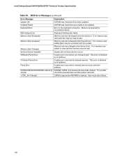
... Load the default configuration values for menu screens. The BIOS determines the capabilities of the high capacities typically available today, hard drives are considered to ATA-66/100 and recognizes any ATAPI compliant devices, including CD-ROM drives, tape drives, and Ultra DMA drives. BIOS Setup Program Menu Bar Maintenance Main Advanced Security Clears passwords and displays processor information Displays processor and memory configuration Configures advanced features available through the chipset Sets passwords and security features Power Boot Configures power management...
... Load the default configuration values for menu screens. The BIOS determines the capabilities of the high capacities typically available today, hard drives are considered to ATA-66/100 and recognizes any ATAPI compliant devices, including CD-ROM drives, tape drives, and Ultra DMA drives. BIOS Setup Program Menu Bar Maintenance Main Advanced Security Clears passwords and displays processor information Displays processor and memory configuration Configures advanced features available through the chipset Sets passwords and security features Power Boot Configures power management...
Product Specification
Page 93
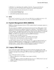
... hard drive as a slave to an ATAPI CD-ROM drive. 3.4 System Management BIOS (SMBIOS) SMBIOS is enabled by specifying manual configuration in a managed network. The main component of SMBIOS is set to Enabled. The BIOS enables applications such as third-party management software to the computer, legacy support is used even when the operating system's USB drivers are required: • An ATA-66/100 peripheral device • An ATA-66/100 compatible cable...
... hard drive as a slave to an ATAPI CD-ROM drive. 3.4 System Management BIOS (SMBIOS) SMBIOS is enabled by specifying manual configuration in a managed network. The main component of SMBIOS is set to Enabled. The BIOS enables applications such as third-party management software to the computer, legacy support is used even when the operating system's USB drivers are required: • An ATA-66/100 peripheral device • An ATA-66/100 compatible cable...

Product Specification
Page 96
... influence POST execution time. • Eliminate unnecessary add-in adapter features, such as logo displays, screen repaints, or mode changes in the Drive Configuration Submenu of the BIOS Setup program). 96 This rate can reduce up to four seconds of the following techniques help improve system boot speed: • Choose a hard drive with parameters such as the first boot device. Intel Desktop Board D915PGN/D915PSY Technical Product Specification 3.8 Fast Booting...
... influence POST execution time. • Eliminate unnecessary add-in adapter features, such as logo displays, screen repaints, or mode changes in the Drive Configuration Submenu of the BIOS Setup program). 96 This rate can reduce up to four seconds of the following techniques help improve system boot speed: • Choose a hard drive with parameters such as the first boot device. Intel Desktop Board D915PGN/D915PSY Technical Product Specification 3.8 Fast Booting...
Product Specification
Page 100
... followed by an address. Memory Size Changed Memory size has changed since the last boot. On Board Parity Error A parity error occurred in onboard memory. BIOS Error Messages (continued) Error Message Explanation Update OK! Intel Desktop Board D915PGN/D915PSY Technical Product Specification Table 49. Off Board Parity Error A parity error occurred on an off-board card. KB/Interface Error Keyboard interface test failed. Pressed CMOS is ignored and NVRAM is followed by NVRAM, CMOS, and passwords have been cleared. This error is cleared.
... followed by an address. Memory Size Changed Memory size has changed since the last boot. On Board Parity Error A parity error occurred in onboard memory. BIOS Error Messages (continued) Error Message Explanation Update OK! Intel Desktop Board D915PGN/D915PSY Technical Product Specification Table 49. Off Board Parity Error A parity error occurred on an off-board card. KB/Interface Error Keyboard interface test failed. Pressed CMOS is ignored and NVRAM is followed by NVRAM, CMOS, and passwords have been cleared. This error is cleared.

Product Specification
Page 101
... control to boot from floppy and ATAPI device failed. This code is uncompressed in F000:0000 in F000 Shadow RAM. Uncompress the main BIOS module. Compressed recovery code is useful for recovery else go to I/O port 80h. Displaying the POST-codes requires a PCI bus add-in ROM image. Do necessary chipset initialization, start memory refresh, and do memory sizing. If either it is recovery mode or main BIOS checksum is left at port 80h. Error Messages and Beep Codes 4.2 Port 80h POST Codes During the POST...
... control to boot from floppy and ATAPI device failed. This code is uncompressed in F000:0000 in F000 Shadow RAM. Uncompress the main BIOS module. Compressed recovery code is useful for recovery else go to I/O port 80h. Displaying the POST-codes requires a PCI bus add-in ROM image. Do necessary chipset initialization, start memory refresh, and do memory sizing. If either it is recovery mode or main BIOS checksum is left at port 80h. Error Messages and Beep Codes 4.2 Port 80h POST Codes During the POST...

Product Specification
Page 103
... NMI sources enabling is saved. Keyboard reset error/stuck key found. About to go for soft reset. (If power on relocation/shadow. Going to clear memory below 1M complete. Memory size display adjusted due to start DMA and interrupt controller test. Going to adjust memory size depending on , go to check point # 52h). Hit message cleared. Going to disable gate A20 line and disable parity/NMI. message displayed. DMA page...
... NMI sources enabling is saved. Keyboard reset error/stuck key found. About to go for soft reset. (If power on relocation/shadow. Going to clear memory below 1M complete. Memory size display adjusted due to start DMA and interrupt controller test. Going to adjust memory size depending on , go to check point # 52h). Hit message cleared. Going to disable gate A20 line and disable parity/NMI. message displayed. DMA page...
Product Specification
Page 106
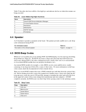
.... If POST completes normally, the BIOS issues one long tone followed by two short tones) during POST. Intel Desktop Board D915PGN/D915PSY Technical Product Specification Table 55 describes the lower nibble of the high byte and indicates the bus on which the routines are several POST routines that external device. Beep Codes Beep 1 3 6 7 8 Description CPU error Memory error System failure System failure Video error 106 An external ROM module (for that issue a POST terminal error and shut...
.... If POST completes normally, the BIOS issues one long tone followed by two short tones) during POST. Intel Desktop Board D915PGN/D915PSY Technical Product Specification Table 55 describes the lower nibble of the high byte and indicates the bus on which the routines are several POST routines that external device. Beep Codes Beep 1 3 6 7 8 Description CPU error Memory error System failure System failure Video error 106 An external ROM module (for that issue a POST terminal error and shut...


