
User Manual
Page 1
® P4T-M Intel® 850 Micro-ATX Motherboard USER'S MANUAL ASUS P4T-M User's Manual 1
® P4T-M Intel® 850 Micro-ATX Motherboard USER'S MANUAL ASUS P4T-M User's Manual 1
User Manual
Page 4
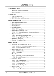
... 4.4.3 PCI Configuration 58 4.4.4 Shadow Configuration 60 4.5 Power Menu 61 4.5.1 Power Up Control 63 4 ASUS P4T-M User's Manual HARDWARE SETUP 14 3.1 P4T-M Motherboard Layout 14 3.2 Layout Contents 15 3.3 Getting Started 16 3.4 System Memory 17 3.5.1 CPU Installation 19 3.5 Central Processing Unit (CPU 19 3.5.2 CPU Heatsink Retention ... for Expansion Cards 24 3.7 External Connectors 26 3.8 Starting Up the First Time 37 4. FEATURES 8 2.1 The ASUS P4T-M 8 2.2 P4T-M Motherboard Components 12 3. INTRODUCTION 7 1.1 How This Manual Is Organized 7 1.2 Item Checklist 7 2.
... 4.4.3 PCI Configuration 58 4.4.4 Shadow Configuration 60 4.5 Power Menu 61 4.5.1 Power Up Control 63 4 ASUS P4T-M User's Manual HARDWARE SETUP 14 3.1 P4T-M Motherboard Layout 14 3.2 Layout Contents 15 3.3 Getting Started 16 3.4 System Memory 17 3.5.1 CPU Installation 19 3.5 Central Processing Unit (CPU 19 3.5.2 CPU Heatsink Retention ... for Expansion Cards 24 3.7 External Connectors 26 3.8 Starting Up the First Time 37 4. FEATURES 8 2.1 The ASUS P4T-M 8 2.2 P4T-M Motherboard Components 12 3. INTRODUCTION 7 1.1 How This Manual Is Organized 7 1.2 Item Checklist 7 2.

User Manual
Page 5
SOFTWARE REFERENCE 73 6.2 ASUS PC Probe 73 6.3 CyberLink PowerPlayer SE 78 6.4 CyberLink VideoLive Mail 79 7. APPENDIX 81 7.1 Glossary 81 INDEX 85 ASUS P4T-M User's Manual 5 CONTENTS 4.5.2 Hardware Monitor 64 4.6 Boot Menu 65 4.7 Exit Menu 67 5. SOFTWARE SETUP 69 5.1 Install Operating System 69 5.2 Start Windows 69 5.3 P4T-M Motherboard Support CD 70 6.1 ASUS Live Update 72 6.
SOFTWARE REFERENCE 73 6.2 ASUS PC Probe 73 6.3 CyberLink PowerPlayer SE 78 6.4 CyberLink VideoLive Mail 79 7. APPENDIX 81 7.1 Glossary 81 INDEX 85 ASUS P4T-M User's Manual 5 CONTENTS 4.5.2 Hardware Monitor 64 4.6 Boot Menu 65 4.7 Exit Menu 67 5. SOFTWARE SETUP 69 5.1 Install Operating System 69 5.2 Start Windows 69 5.3 P4T-M Motherboard Support CD 70 6.1 ASUS Live Update 72 6.
User Manual
Page 7
...RIMM (1) ASUS 2-port USB connector set with bracket (1) I/O port bracket (1) Bag of spare jumpers (1) Support drivers and utilities (1) This Motherboard User's Manual (1) CPU Heatsink Retention Module (1) Quick Setup Manual (1) Reference Card Optional Items ASUS IrDA-compliant infrared module ASUS P4T-M User...'s Manual 7 Package Contents (1) ASUS Motherboard (1) 40-pin 80-conductor ribbon cable for internal UltraDMA33/ 66/100 IDE drives (1) Ribbon cable for the included software Optional...
...RIMM (1) ASUS 2-port USB connector set with bracket (1) I/O port bracket (1) Bag of spare jumpers (1) Support drivers and utilities (1) This Motherboard User's Manual (1) CPU Heatsink Retention Module (1) Quick Setup Manual (1) Reference Card Optional Items ASUS IrDA-compliant infrared module ASUS P4T-M User...'s Manual 7 Package Contents (1) ASUS Motherboard (1) 40-pin 80-conductor ribbon cable for internal UltraDMA33/ 66/100 IDE drives (1) Ribbon cable for the included software Optional...
User Manual
Page 8
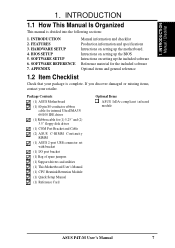
... allows burst mode data transfer rates of 4 USB ports for more peripheral connectivity options. • Wake-Up Support: Supports Wake-On-LAN, Keyboard Wake-Up, and BIOS Wake-Up. • PC Health Monitoring: An easy way to examine and manage system status information... no ISA, eliminating bottlenecks and system memory management issues. FEATURES Specifications 2. 2. FEATURES 2.1 The ASUS P4T-M The ASUS P4T-M motherboard is required. • Intel® Accelerated Hub Architecture: Features a dedicated high speed hub link between the ICH2 and MCH with an Accelerated Graphics Port 4X ...
... allows burst mode data transfer rates of 4 USB ports for more peripheral connectivity options. • Wake-Up Support: Supports Wake-On-LAN, Keyboard Wake-Up, and BIOS Wake-Up. • PC Health Monitoring: An easy way to examine and manage system status information... no ISA, eliminating bottlenecks and system memory management issues. FEATURES Specifications 2. 2. FEATURES 2.1 The ASUS P4T-M The ASUS P4T-M motherboard is required. • Intel® Accelerated Hub Architecture: Features a dedicated high speed hub link between the ICH2 and MCH with an Accelerated Graphics Port 4X ...
User Manual
Page 9
... isochronous (real-time) data transfer. UART2 can also be directed from PCI master bus to -use interface which provides more control and protection over the motherboard.
... isochronous (real-time) data transfer. UART2 can also be directed from PCI master bus to -use interface which provides more control and protection over the motherboard.
User Manual
Page 10
...33, and DMA and with two connectors that you do not have to be ready around the clock, yet satisfy all ASUS smart series motherboards. To realize the benefits of ACPI, an ACPI-supported OS, such as Windows 98/ 2000/Millenium, must be used. • Suspend... Compliancy: Both the BIOS and hardware levels of 0.8GB/s, MCH dual channel Rambus DRAMs can be enabled.) • RDRAM Optimized Performance: This motherboard supports the new generation memory, Rambus Dynamic Random Access Memory (RDRAM). With these features implemented in two channels. 2. While PC100 SDRAM modules operate...
...33, and DMA and with two connectors that you do not have to be ready around the clock, yet satisfy all ASUS smart series motherboards. To realize the benefits of ACPI, an ACPI-supported OS, such as Windows 98/ 2000/Millenium, must be used. • Suspend... Compliancy: Both the BIOS and hardware levels of 0.8GB/s, MCH dual channel Rambus DRAMs can be enabled.) • RDRAM Optimized Performance: This motherboard supports the new generation memory, Rambus Dynamic Random Access Memory (RDRAM). With these features implemented in two channels. 2. While PC100 SDRAM modules operate...
User Manual
Page 11
... is necessary to ensure proper system configuration and management. • System Resources Alert: Today's operating systems, such as the Soft-Off (see ATX Power / Soft-Off Switch Lead in conjunction with throttle down to 50% of its duty cycle when the CPU temperature reaches the threshold and ..., pushing the power button for future processors, so monitoring is enabled, the CPU with either the bundled ASUS PC Probe or Intel LDCM will enter the Soft-Off mode. • Peripheral Power Up: Keyboard or Mouse power up to critical motherboard components. 2. ASUS P4T-M User's Manual 11
... is necessary to ensure proper system configuration and management. • System Resources Alert: Today's operating systems, such as the Soft-Off (see ATX Power / Soft-Off Switch Lead in conjunction with throttle down to 50% of its duty cycle when the CPU temperature reaches the threshold and ..., pushing the power button for future processors, so monitoring is enabled, the CPU with either the bundled ASUS PC Probe or Intel LDCM will enter the Soft-Off mode. • Peripheral Power Up: Keyboard or Mouse power up to critical motherboard components. 2. ASUS P4T-M User's Manual 11
User Manual
Page 12
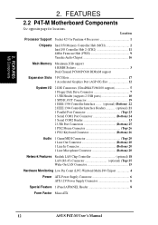
FEATURES 2.2 P4T-M Motherboard Components See opposite page for Pentium 4 Processors 1 Chipsets Intel 850 Memory Controller Hub (MCH 2 Intel I/O Controller Hub 2 (ICH2 11 4Mbit Firmware Hub (FWH 9 Yamaha Audio Chipset 16 Main Memory Maximum 2GB support 4...1 Line Microphone Connector Bottom) 20 Network Features Realtek LAN Chip Controller optional) 18 LAN (RJ-45) Connector optional) (Top) 25 Wake-On-LAN Connector 15 Hardware Monitoring Low Pin Count (LPC) Winbond Multi-I/O Chipset 4 Power ATX Power Supply Connector 6 ATX 12V Power Supply Connector 6 Special Feature 1 iPanel ...
FEATURES 2.2 P4T-M Motherboard Components See opposite page for Pentium 4 Processors 1 Chipsets Intel 850 Memory Controller Hub (MCH 2 Intel I/O Controller Hub 2 (ICH2 11 4Mbit Firmware Hub (FWH 9 Yamaha Audio Chipset 16 Main Memory Maximum 2GB support 4...1 Line Microphone Connector Bottom) 20 Network Features Realtek LAN Chip Controller optional) 18 LAN (RJ-45) Connector optional) (Top) 25 Wake-On-LAN Connector 15 Hardware Monitoring Low Pin Count (LPC) Winbond Multi-I/O Chipset 4 Power ATX Power Supply Connector 6 ATX 12V Power Supply Connector 6 Special Feature 1 iPanel ...
User Manual
Page 14
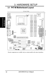
...Manual HARDWARE SETUP 3.1 P4T-M Motherboard Layout PS/2KBMS T: Mouse B: Keyboard Bottom: Top: USB1 RJ-45 USB2 COM1 24.4cm (9.60in) CPU_FAN Multi I/O ATX12V ATX Power Connector PARALLEL PORT Socket 423 PWR_FAN SECONDARY IDE GAME_AUDIO IEEE1394 Line Out Line In 1394HEAD3 Intel 850 Memory Controller Hub (MCH... WOLCON Audio Codec CD_IN PCI3 1394 Link Layer Chip CR2032 3V Lithium Cell CMOS Power Intel I/O Controller Hub (ICH2) 4Mbit Firmware Hub CHA_FAN IR BUZZER CLRTC USB2 AFPANEL P4T-M COM2 IDELED PANEL Grayed components are available only on certain models at the...
...Manual HARDWARE SETUP 3.1 P4T-M Motherboard Layout PS/2KBMS T: Mouse B: Keyboard Bottom: Top: USB1 RJ-45 USB2 COM1 24.4cm (9.60in) CPU_FAN Multi I/O ATX12V ATX Power Connector PARALLEL PORT Socket 423 PWR_FAN SECONDARY IDE GAME_AUDIO IEEE1394 Line Out Line In 1394HEAD3 Intel 850 Memory Controller Hub (MCH... WOLCON Audio Codec CD_IN PCI3 1394 Link Layer Chip CR2032 3V Lithium Cell CMOS Power Intel I/O Controller Hub (ICH2) 4Mbit Firmware Hub CHA_FAN IR BUZZER CLRTC USB2 AFPANEL P4T-M COM2 IDELED PANEL Grayed components are available only on certain models at the...
User Manual
Page 16
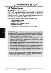
... that you unplug your computer, you work on your motherboard, peripherals, and/or components. 16 ASUS P4T-M User's Manual H/W SETUP Getting Started 3. If you plug in or remove the ATX power connector on the +12V lead is switched off before handling computer components. Hold ... the power supply case. 3. Make sure that the ATX power supply is required. Unplug your computer when working on the bag that can supply at least 230W and at least 300W is recommended for this motherboard. Computer motherboards and expansion cards contain very delicate Integrated Circuit (IC)...
... that you unplug your computer, you work on your motherboard, peripherals, and/or components. 16 ASUS P4T-M User's Manual H/W SETUP Getting Started 3. If you plug in or remove the ATX power connector on the +12V lead is switched off before handling computer components. Hold ... the power supply case. 3. Make sure that the ATX power supply is required. Unplug your computer when working on the bag that can supply at least 230W and at least 300W is recommended for this motherboard. Computer motherboards and expansion cards contain very delicate Integrated Circuit (IC)...

User Manual
Page 17
... RDRAM technologies. nel B (RIMMB1 and RIMMB2) must be inserted into RIMMA2 and RIMMB2. When C-RIMMs are a serial connection in this motherboard. HARDWARE SETUP 3.4 System Memory NOTE: No hardware or BIOS setup is recommended that you use when socket will not be identical (see below). ...2. This motherboard has four 184-pin Rambus Inline Memory Modules (RIMM) sockets. Location Memory Module Subtotal RIMMA1 (Rows 0&1) RDRAM x 1 C-RIMM (use when...
... RDRAM technologies. nel B (RIMMB1 and RIMMB2) must be inserted into RIMMA2 and RIMMB2. When C-RIMMs are a serial connection in this motherboard. HARDWARE SETUP 3.4 System Memory NOTE: No hardware or BIOS setup is recommended that you use when socket will not be identical (see below). ...2. This motherboard has four 184-pin Rambus Inline Memory Modules (RIMM) sockets. Location Memory Module Subtotal RIMMA1 (Rows 0&1) RDRAM x 1 C-RIMM (use when...
User Manual
Page 19
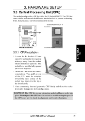
... lever until it snaps into place. CAUTION! If not, then purchase a fan before turning on the system. HARDWARE SETUP 3.5 Central Processing Unit (CPU) The motherboard provides a ZIF Socket for bent pins. If the CPU does not fit, check its locked position. 3. Insert the CPU with the... motherboard should drop easily into its alignment and look for the P4 Socket 423 CPU. The CPU fits in one orientation and should have a fan attached to it by pulling the lever...
... lever until it snaps into place. CAUTION! If not, then purchase a fan before turning on the system. HARDWARE SETUP 3.5 Central Processing Unit (CPU) The motherboard provides a ZIF Socket for bent pins. If the CPU does not fit, check its locked position. 3. Insert the CPU with the... motherboard should drop easily into its alignment and look for the P4 Socket 423 CPU. The CPU fits in one orientation and should have a fan attached to it by pulling the lever...
User Manual
Page 20
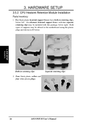
Both types of supports may be included with two separate retaining clips may be affixed to the motherboard using the plastic plugs and shown in #2 below. 3. HARDWARE SETUP 3.5.2 CPU Heatsink Retention Module Installation Parts Inventory: 1. H/W SETUP Heatskink Built-in retaining clips, below right. Two black plastic heatsink support braces have built-in retaining clips 2. Four black plastic collars and four white plastic plugs. Separate retaining clips 20 ASUS P4T-M User's Manual An alternate heatsink support brace with this package, below left. 3.
Both types of supports may be included with two separate retaining clips may be affixed to the motherboard using the plastic plugs and shown in #2 below. 3. HARDWARE SETUP 3.5.2 CPU Heatsink Retention Module Installation Parts Inventory: 1. H/W SETUP Heatskink Built-in retaining clips, below right. Two black plastic heatsink support braces have built-in retaining clips 2. Four black plastic collars and four white plastic plugs. Separate retaining clips 20 ASUS P4T-M User's Manual An alternate heatsink support brace with this package, below left. 3.
User Manual
Page 21
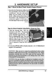
... of heatsink support clips in retaining clips, right. Place the heatsink on the CPU. This instruction applies to the fan connector. (See 3.1 Motherboard Layout / 3.8 Connectors). The plastic heatsink support braces have built-in steps 2a and 2b. 3. Connect the CPU fan cable to both the... processor and the motherboard. Be sure that there is sufficient air circulation across the processor's heatsink by regularly checking that your CPU, make sure that exposed CPU...
... of heatsink support clips in retaining clips, right. Place the heatsink on the CPU. This instruction applies to the fan connector. (See 3.1 Motherboard Layout / 3.8 Connectors). The plastic heatsink support braces have built-in steps 2a and 2b. 3. Connect the CPU fan cable to both the... processor and the motherboard. Be sure that there is sufficient air circulation across the processor's heatsink by regularly checking that your CPU, make sure that exposed CPU...
User Manual
Page 22
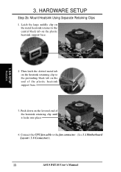
... the heatsink retaining clip until it locks into place. 4. Then latch the slotted metal tab on the heatsink retaining clip to the fan connector. (See 3.1 Motherboard Layout / 3.8 Connectors). 22 ASUS P4T-M User's Manual HARDWARE SETUP Step 2b: Mount Heatsink Using Separate Retaining Clips 1. Connect the CPU fan cable to the protruding...
... the heatsink retaining clip until it locks into place. 4. Then latch the slotted metal tab on the heatsink retaining clip to the fan connector. (See 3.1 Motherboard Layout / 3.8 Connectors). 22 ASUS P4T-M User's Manual HARDWARE SETUP Step 2b: Mount Heatsink Using Separate Retaining Clips 1. Connect the CPU fan cable to the protruding...
User Manual
Page 23
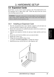
The motherboard has five PCI expansion slots to the slot with the screw you removed earlier. 5. Secure the card to support these cards. Follow the steps in ... components. Replace the system cover. 6. Install the necessary software drivers for the card before installing it. 2. Failure to do so may need to both the motherboard and expansion cards. 3.6.1 Installing an Expansion Card 1. Read the documentation that comes with the slot and press firmly until the card fits in the next...
The motherboard has five PCI expansion slots to the slot with the screw you removed earlier. 5. Secure the card to support these cards. Follow the steps in ... components. Replace the system cover. 6. Install the necessary software drivers for the card before installing it. 2. Failure to do so may need to both the motherboard and expansion cards. 3.6.1 Installing an Expansion Card 1. Read the documentation that comes with the slot and press firmly until the card fits in the next...
User Manual
Page 24
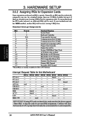
...-- -- In a standard design, there are 16 IRQs available but most of them are usually available for this Motherboard PCI slot 1 PCI slot 2 PCI slot 3 AGP slot USB HC0 USB HC1 SMB AC'97 LAN IEEE 1394 INT-A INT-B -- -- -- INT-C INT-D INT-E INT-F - - - Conflicts will arise ...INT-G INT-H -- 3. H/W SETUP Expansion Cards 3. Generally, an IRQ must be used - - - If your motherboard also has MIDI enabled, another IRQ will be exclusively assigned to operate. If your motherboard has PCI audio onboard, an additional IRQ will make sure that the drivers support "Share IRQ" or that...
...-- -- In a standard design, there are 16 IRQs available but most of them are usually available for this Motherboard PCI slot 1 PCI slot 2 PCI slot 3 AGP slot USB HC0 USB HC1 SMB AC'97 LAN IEEE 1394 INT-A INT-B -- -- -- INT-C INT-D INT-E INT-F - - - Conflicts will arise ...INT-G INT-H -- 3. H/W SETUP Expansion Cards 3. Generally, an IRQ must be used - - - If your motherboard also has MIDI enabled, another IRQ will be exclusively assigned to operate. If your motherboard has PCI audio onboard, an additional IRQ will make sure that the drivers support "Share IRQ" or that...
User Manual
Page 25
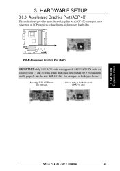
... AGP cards only operate at 3.3 volts and will not fit properly into the new AGP 4X slots. HARDWARE SETUP 3.6.3 Accelerated Graphics Port (AGP 4X) This motherboard provides an accelerated graphics port (AGP 4X) to use . A new 1.5 / 3.3V AGP card: OKAY to support a new generation of both 1.5 and 3.3 Volts. P4T-M P4T-M Accelerated...
... AGP cards only operate at 3.3 volts and will not fit properly into the new AGP 4X slots. HARDWARE SETUP 3.6.3 Accelerated Graphics Port (AGP 4X) This motherboard provides an accelerated graphics port (AGP 4X) to use . A new 1.5 / 3.3V AGP card: OKAY to support a new generation of both 1.5 and 3.3 Volts. P4T-M P4T-M Accelerated...
User Manual
Page 26
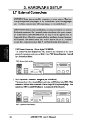
Check the connectors before installation because there may be less than 15 cm (6 in.) from jumpers in the Motherboard Layout. See PS/2 Mouse Function Control in .), with the red stripe to mini DIN adapter on standard AT keyboards. PS/2 Keyboard (6-pin... exceptions. 3. Placing jumper caps over these connector pins will not allow standard AT size (large DIN) keyboard plugs. This connector will cause damage to your motherboard. H/W SETUP Connectors 2) PS/2 Keyboard Connector (Purple 6-pin PS2KBMS) This connection is not detected, expansion cards can use a DIN to Pin 1 on ...
Check the connectors before installation because there may be less than 15 cm (6 in.) from jumpers in the Motherboard Layout. See PS/2 Mouse Function Control in .), with the red stripe to mini DIN adapter on standard AT keyboards. PS/2 Keyboard (6-pin... exceptions. 3. Placing jumper caps over these connector pins will not allow standard AT size (large DIN) keyboard plugs. This connector will cause damage to your motherboard. H/W SETUP Connectors 2) PS/2 Keyboard Connector (Purple 6-pin PS2KBMS) This connection is not detected, expansion cards can use a DIN to Pin 1 on ...


