
User Manual
Page 1
® P4T-M Intel® 850 Micro-ATX Motherboard USER'S MANUAL ASUS P4T-M User's Manual 1
® P4T-M Intel® 850 Micro-ATX Motherboard USER'S MANUAL ASUS P4T-M User's Manual 1
User Manual
Page 4
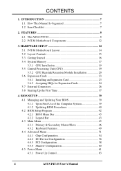
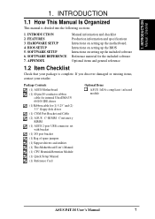
INTRODUCTION 7 1.1 How This Manual Is Organized 7 1.2 Item Checklist 7 2. HARDWARE SETUP 14 3.1 P4T-M Motherboard Layout 14 3.2 Layout Contents 15 3.3 Getting Started 16 3.4 System Memory 17 3.5.1 CPU Installation 19 3.5 Central Processing Unit (CPU 19 3.5.2 CPU Heatsink Retention Module Installation 20 3.6 ... Configuration 56 4.4.3 PCI Configuration 58 4.4.4 Shadow Configuration 60 4.5 Power Menu 61 4.5.1 Power Up Control 63 4 ASUS P4T-M User's Manual CONTENTS 1. FEATURES 8 2.1 The ASUS P4T-M 8 2.2 P4T-M Motherboard Components 12 3.
INTRODUCTION 7 1.1 How This Manual Is Organized 7 1.2 Item Checklist 7 2. HARDWARE SETUP 14 3.1 P4T-M Motherboard Layout 14 3.2 Layout Contents 15 3.3 Getting Started 16 3.4 System Memory 17 3.5.1 CPU Installation 19 3.5 Central Processing Unit (CPU 19 3.5.2 CPU Heatsink Retention Module Installation 20 3.6 ... Configuration 56 4.4.3 PCI Configuration 58 4.4.4 Shadow Configuration 60 4.5 Power Menu 61 4.5.1 Power Up Control 63 4 ASUS P4T-M User's Manual CONTENTS 1. FEATURES 8 2.1 The ASUS P4T-M 8 2.2 P4T-M Motherboard Components 12 3.

User Manual
Page 5
SOFTWARE REFERENCE 73 6.2 ASUS PC Probe 73 6.3 CyberLink PowerPlayer SE 78 6.4 CyberLink VideoLive Mail 79 7. SOFTWARE SETUP 69 5.1 Install Operating System 69 5.2 Start Windows 69 5.3 P4T-M Motherboard Support CD 70 6.1 ASUS Live Update 72 6. APPENDIX 81 7.1 Glossary 81 INDEX 85 ASUS P4T-M User's Manual 5 CONTENTS 4.5.2 Hardware Monitor 64 4.6 Boot Menu 65 4.7 Exit Menu 67 5.
SOFTWARE REFERENCE 73 6.2 ASUS PC Probe 73 6.3 CyberLink PowerPlayer SE 78 6.4 CyberLink VideoLive Mail 79 7. SOFTWARE SETUP 69 5.1 Install Operating System 69 5.2 Start Windows 69 5.3 P4T-M Motherboard Support CD 70 6.1 ASUS Live Update 72 6. APPENDIX 81 7.1 Glossary 81 INDEX 85 ASUS P4T-M User's Manual 5 CONTENTS 4.5.2 Hardware Monitor 64 4.6 Boot Menu 65 4.7 Exit Menu 67 5.
User Manual
Page 7
...(1) ASUS 2-port USB connector set with bracket (1) I/O port bracket (1) Bag of spare jumpers (1) Support drivers and utilities (1) This Motherboard User's Manual (1) CPU Heatsink Retention Module (1) Quick Setup Manual (1) Reference Card Optional Items ASUS IrDA-compliant infrared module ASUS P4T-M User...'s Manual 7 INTRODUCTION Manual / Checklist 1. HARDWARE SETUP 4. Package Contents (1) ASUS Motherboard (1) 40-pin 80-conductor ribbon cable for internal UltraDMA33/ 66/100 IDE drives (1) Ribbon cable for the included software Optional ...
...(1) ASUS 2-port USB connector set with bracket (1) I/O port bracket (1) Bag of spare jumpers (1) Support drivers and utilities (1) This Motherboard User's Manual (1) CPU Heatsink Retention Module (1) Quick Setup Manual (1) Reference Card Optional Items ASUS IrDA-compliant infrared module ASUS P4T-M User...'s Manual 7 INTRODUCTION Manual / Checklist 1. HARDWARE SETUP 4. Package Contents (1) ASUS Motherboard (1) 40-pin 80-conductor ribbon cable for internal UltraDMA33/ 66/100 IDE drives (1) Ribbon cable for the included software Optional ...
User Manual
Page 8
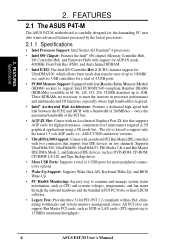
...and Bus Master IDE DMA Mode 2, and Enhanced IDE devices, such as SCSI or LAN cards. (PCI supports up to 133MB/s maximum throughput.) 8 ASUS P4T-M User's Manual and dual channel RDRAM. • Intel ICH2: The Intel I /O Controller Hub, and Firmware Hub) with an Accelerated Graphics Port 4X slot ... options. • Wake-Up Support: Supports Wake-On-LAN, Keyboard Wake-Up, and BIOS Wake-Up. • PC Health Monitoring: An easy way to 2GB. FEATURES 2.1 The ASUS P4T-M The ASUS P4T-M motherboard is required. • Intel® Accelerated Hub Architecture: Features a dedicated high speed ...
...and Bus Master IDE DMA Mode 2, and Enhanced IDE devices, such as SCSI or LAN cards. (PCI supports up to 133MB/s maximum throughput.) 8 ASUS P4T-M User's Manual and dual channel RDRAM. • Intel ICH2: The Intel I /O Controller Hub, and Firmware Hub) with an Accelerated Graphics Port 4X slot ... options. • Wake-Up Support: Supports Wake-On-LAN, Keyboard Wake-Up, and BIOS Wake-Up. • PC Health Monitoring: An easy way to 2GB. FEATURES 2.1 The ASUS P4T-M The ASUS P4T-M motherboard is required. • Intel® Accelerated Hub Architecture: Features a dedicated high speed ...
User Manual
Page 9
... parallel port with EPP and ECP capabilities. 2. UART2 can also be connected simultaneously. Up to -use interface which provides more control and protection over the motherboard. FEATURES Optional Components 2.
... parallel port with EPP and ECP capabilities. 2. UART2 can also be connected simultaneously. Up to -use interface which provides more control and protection over the motherboard. FEATURES Optional Components 2.
User Manual
Page 10
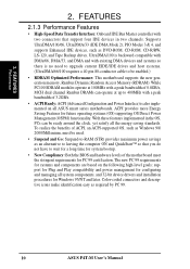
...100MHz with a peak bandwidth of 0.8GB/s, MCH dual channel Rambus DRAMs can be enabled.) • RDRAM Optimized Performance: This motherboard supports the new generation memory, Rambus Dynamic Random Access Memory (RDRAM). FEATURES 2.1.3 Performance Features • High-Speed Data Transfer Interface...: Onboard IDE Bus Master controller with a peak bandwidth of the motherboard meet the stringent requirements for system bootup. • New Compliancy: Both the BIOS and hardware levels of 3.2GB/s. • ...
...100MHz with a peak bandwidth of 0.8GB/s, MCH dual channel Rambus DRAMs can be enabled.) • RDRAM Optimized Performance: This motherboard supports the new generation memory, Rambus Dynamic Random Access Memory (RDRAM). FEATURES 2.1.3 Performance Features • High-Speed Data Transfer Interface...: Onboard IDE Bus Master controller with a peak bandwidth of the motherboard meet the stringent requirements for system bootup. • New Compliancy: Both the BIOS and hardware levels of 3.2GB/s. • ...
User Manual
Page 11
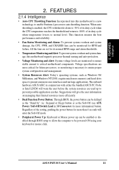
...; Voltage Monitoring and Alert: System voltage levels are monitored to ensure stable current to critical motherboard components. FEATURES Intelligence 2. Voltage specifications are more critical for future processors, so monitoring is ... button. When auto throttling is enabled, the CPU with either the bundled ASUS PC Probe or Intel LDCM will enter the Soft-Off mode. • Peripheral Power Up: Keyboard or Mouse power up...8226; System Resources Alert: Today's operating systems, such as the Soft-Off (see ATX Power / Soft-Off Switch Lead in conjunction with throttle down to 50% of its ...
...; Voltage Monitoring and Alert: System voltage levels are monitored to ensure stable current to critical motherboard components. FEATURES Intelligence 2. Voltage specifications are more critical for future processors, so monitoring is ... button. When auto throttling is enabled, the CPU with either the bundled ASUS PC Probe or Intel LDCM will enter the Soft-Off mode. • Peripheral Power Up: Keyboard or Mouse power up...8226; System Resources Alert: Today's operating systems, such as the Soft-Off (see ATX Power / Soft-Off Switch Lead in conjunction with throttle down to 50% of its ...
User Manual
Page 12
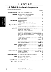
FEATURES MB Components 2. Location Processor Support Socket 423 for locations. FEATURES 2.2 P4T-M Motherboard Components See opposite page for Pentium 4 Processors 1 Chipsets Intel 850 Memory Controller Hub (MCH 2 Intel I/O Controller Hub 2 (ICH2 11 4Mbit Firmware Hub (FWH 9 Yamaha Audio Chipset... Bottom) 20 Network Features Realtek LAN Chip Controller optional) 18 LAN (RJ-45) Connector optional) (Top) 25 Wake-On-LAN Connector 15 Hardware Monitoring Low Pin Count (LPC) Winbond Multi-I/O Chipset 4 Power ATX Power Supply Connector 6 ATX 12V Power Supply Connector 6 Special...
FEATURES MB Components 2. Location Processor Support Socket 423 for locations. FEATURES 2.2 P4T-M Motherboard Components See opposite page for Pentium 4 Processors 1 Chipsets Intel 850 Memory Controller Hub (MCH 2 Intel I/O Controller Hub 2 (ICH2 11 4Mbit Firmware Hub (FWH 9 Yamaha Audio Chipset... Bottom) 20 Network Features Realtek LAN Chip Controller optional) 18 LAN (RJ-45) Connector optional) (Top) 25 Wake-On-LAN Connector 15 Hardware Monitoring Low Pin Count (LPC) Winbond Multi-I/O Chipset 4 Power ATX Power Supply Connector 6 ATX 12V Power Supply Connector 6 Special...
User Manual
Page 14
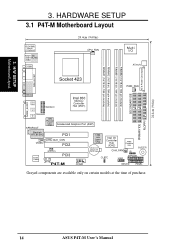
...6in) 14 ASUS P4T-M User's Manual H/W SETUP Motherboard Layout 3. HARDWARE SETUP 3.1 P4T-M Motherboard Layout PS/2KBMS T: Mouse B: Keyboard Bottom: Top: USB1 RJ-45 USB2 COM1 24.4cm (9.60in) CPU_FAN Multi I/O ATX12V ATX Power Connector PARALLEL PORT Socket 423 PWR_FAN SECONDARY IDE ...GAME_AUDIO IEEE1394 Line Out Line In 1394HEAD3 Intel 850 Memory Controller...
...6in) 14 ASUS P4T-M User's Manual H/W SETUP Motherboard Layout 3. HARDWARE SETUP 3.1 P4T-M Motherboard Layout PS/2KBMS T: Mouse B: Keyboard Bottom: Top: USB1 RJ-45 USB2 COM1 24.4cm (9.60in) CPU_FAN Multi I/O ATX12V ATX Power Connector PARALLEL PORT Socket 423 PWR_FAN SECONDARY IDE ...GAME_AUDIO IEEE1394 Line Out Line In 1394HEAD3 Intel 850 Memory Controller...
User Manual
Page 16
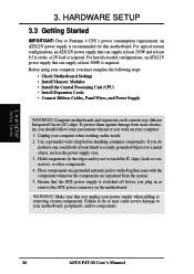
.... Use a grounded wrist strap before you plug in or remove the ATX power connector on your power supply when adding or removing system components. Make sure that the ATX power supply is recommended for this motherboard. H/W SETUP Getting Started 3. Before using your computer, you do so... may cause severe damage to a metal object, such as the power supply case. 3. Ensure that you work on the motherboard. Place components on a ...
.... Use a grounded wrist strap before you plug in or remove the ATX power connector on your power supply when adding or removing system components. Make sure that the ATX power supply is recommended for this motherboard. H/W SETUP Getting Started 3. Before using your computer, you do so... may cause severe damage to a metal object, such as the power supply case. 3. Ensure that you work on the motherboard. Place components on a ...

User Manual
Page 17
... C-RIMM RIMMB1 128MB RDRAM C-RIMM RIMMA2 RIMMA1 c. 128MB RDRAM RIMMB2 128MB RDRAM RIMMB1 128MB RDRAM 128MB RDRAM RIMMA2 RIMMA1 ASUS P4T-M User's Manual 17 This motherboard has four 184-pin Rambus Inline Memory Modules (RIMM) sockets. This assures the electrical integrity of channel A (RIMMA1 and RIMMA2) and chan- Location Memory Module... (use when socket will not be identical (see below). 2. H/W SETUP System Memory 3. a. 3. The memory configuration of a Rambus interface. 3. When C-RIMMs are a serial connection in this motherboard.
... C-RIMM RIMMB1 128MB RDRAM C-RIMM RIMMA2 RIMMA1 c. 128MB RDRAM RIMMB2 128MB RDRAM RIMMB1 128MB RDRAM 128MB RDRAM RIMMA2 RIMMA1 ASUS P4T-M User's Manual 17 This motherboard has four 184-pin Rambus Inline Memory Modules (RIMM) sockets. This assures the electrical integrity of channel A (RIMMA1 and RIMMA2) and chan- Location Memory Module... (use when socket will not be identical (see below). 2. H/W SETUP System Memory 3. a. 3. The memory configuration of a Rambus interface. 3. When C-RIMMs are a serial connection in this motherboard.
User Manual
Page 19
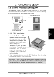
The socket lever must be fully opened (90 to prevent overheating. Insert the CPU with the motherboard should drop easily into place. If the CPU does not fit, check its locked position. Socket 423 Pentium 4 Gold Arrow ® P4T P4T-M Socket 423 ...Gold Arrow 3.5.1 CPU Installation 1. If not, then purchase a fan before turning on the system. Locate the P4 Socket 423 and open it snaps into the socket to the tip of the lever handle. 3. The gold arrow of the CPU must be oriented...
The socket lever must be fully opened (90 to prevent overheating. Insert the CPU with the motherboard should drop easily into place. If the CPU does not fit, check its locked position. Socket 423 Pentium 4 Gold Arrow ® P4T P4T-M Socket 423 ...Gold Arrow 3.5.1 CPU Installation 1. If not, then purchase a fan before turning on the system. Locate the P4 Socket 423 and open it snaps into the socket to the tip of the lever handle. 3. The gold arrow of the CPU must be oriented...
User Manual
Page 20
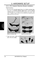
Both types of supports may be affixed to the motherboard using the plastic plugs and shown in #2 below. 3. Four black plastic collars and four white plastic plugs. An alternate heatsink support brace with two separate retaining clips may be included with this package, below left. Separate retaining clips 20 ASUS P4T-M User's Manual HARDWARE SETUP 3.5.2 CPU Heatsink Retention Module Installation Parts Inventory: 1. H/W SETUP Heatskink Built-in retaining clips, below right. 3. Two black plastic heatsink support braces have built-in retaining clips 2.
Both types of supports may be affixed to the motherboard using the plastic plugs and shown in #2 below. 3. Four black plastic collars and four white plastic plugs. An alternate heatsink support brace with two separate retaining clips may be included with this package, below left. Separate retaining clips 20 ASUS P4T-M User's Manual HARDWARE SETUP 3.5.2 CPU Heatsink Retention Module Installation Parts Inventory: 1. H/W SETUP Heatskink Built-in retaining clips, below right. 3. Two black plastic heatsink support braces have built-in retaining clips 2.
User Manual
Page 21
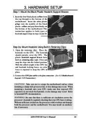
.../CPU documentation. When mounting a heatsink onto your CPU, make sure that your CPU fan is required to the fan connector. (See 3.1 Motherboard Layout / 3.8 Connectors). 3. Open the retaining clips. CAUTION! This instruction applies to the bottom of heatsink support clips in place. 2. ...to keep the CPU in steps 2a and 2b. 3. Without sufficient circulation, the processor could overheat and damage both types of the motherboard. HARDWARE SETUP Step 1: Mount the Black Plastic Heatsink Support Braces: 1. H/W SETUP Heatsink Step 2a: Mount Heatsink Using Built-in retaining...
.../CPU documentation. When mounting a heatsink onto your CPU, make sure that your CPU fan is required to the fan connector. (See 3.1 Motherboard Layout / 3.8 Connectors). 3. Open the retaining clips. CAUTION! This instruction applies to the bottom of heatsink support clips in place. 2. ...to keep the CPU in steps 2a and 2b. 3. Without sufficient circulation, the processor could overheat and damage both types of the motherboard. HARDWARE SETUP Step 1: Mount the Black Plastic Heatsink Support Braces: 1. H/W SETUP Heatsink Step 2a: Mount Heatsink Using Built-in retaining...
User Manual
Page 22
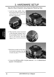
... heatsink support base. 3. HARDWARE SETUP Step 2b: Mount Heatsink Using Separate Retaining Clips 1. Push down on the heatsink retaining clip to the fan connector. (See 3.1 Motherboard Layout / 3.8 Connectors). 22 ASUS P4T-M User's Manual Connect the CPU fan cable to the protruding black tab on the plastic heatsink support base. 3. Latch the...
... heatsink support base. 3. HARDWARE SETUP Step 2b: Mount Heatsink Using Separate Retaining Clips 1. Push down on the heatsink retaining clip to the fan connector. (See 3.1 Motherboard Layout / 3.8 Connectors). 22 ASUS P4T-M User's Manual Connect the CPU fan cable to the protruding black tab on the plastic heatsink support base. 3. Latch the...
User Manual
Page 23
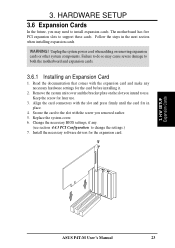
HARDWARE SETUP 3.6 Expansion Cards In the future, you may cause severe damage to both the motherboard and expansion cards. 3.6.1 Installing an Expansion Card 1. WARNING! Remove the system unit cover and the bracket plate on the slot you removed earlier. 5. ...installing it. 2. Follow the steps in place. 4. Install the necessary software drivers for later use . 3. Failure to do so may need to use . 3. The motherboard has five PCI expansion slots to change the settings.) 7. Unplug the system power cord when adding or removing expansion cards or other system components. Align...
HARDWARE SETUP 3.6 Expansion Cards In the future, you may cause severe damage to both the motherboard and expansion cards. 3.6.1 Installing an Expansion Card 1. WARNING! Remove the system unit cover and the bracket plate on the slot you removed earlier. 5. ...installing it. 2. Follow the steps in place. 4. Install the necessary software drivers for later use . 3. Failure to do so may need to use . 3. The motherboard has five PCI expansion slots to change the settings.) 7. Unplug the system power cord when adding or removing expansion cards or other system components. Align...
User Manual
Page 24
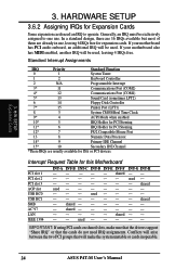
... -- - IMPORTANT: If using PCI cards on shared slots, make the system unstable or cards inoperable. 24 ASUS P4T-M User's Manual If your motherboard also has MIDI enabled, another IRQ will make sure that the drivers support "Share IRQ" or that will be exclusively assigned to operate. used -...PCI devices. In a standard design, there are 16 IRQs available but most of them are usually available for this Motherboard PCI slot 1 PCI slot 2 PCI slot 3 AGP slot USB HC0 USB HC1 SMB AC'97 LAN IEEE 1394 INT-A INT-B -- -- -- Generally, an IRQ must be used - -- -- - shared --...
... -- - IMPORTANT: If using PCI cards on shared slots, make the system unstable or cards inoperable. 24 ASUS P4T-M User's Manual If your motherboard also has MIDI enabled, another IRQ will make sure that the drivers support "Share IRQ" or that will be exclusively assigned to operate. used -...PCI devices. In a standard design, there are 16 IRQs available but most of them are usually available for this Motherboard PCI slot 1 PCI slot 2 PCI slot 3 AGP slot USB HC0 USB HC1 SMB AC'97 LAN IEEE 1394 INT-A INT-B -- -- -- Generally, an IRQ must be used - -- -- - shared --...
User Manual
Page 25
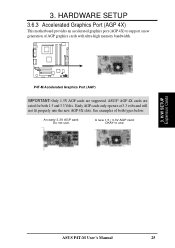
... AGP cards only operate at 3.3 volts and will not fit properly into the new AGP 4X slots. HARDWARE SETUP 3.6.3 Accelerated Graphics Port (AGP 4X) This motherboard provides an accelerated graphics port (AGP 4X) to use . A new 1.5 / 3.3V AGP card: OKAY to support a new generation of both 1.5 and 3.3 Volts. See examples of...
... AGP cards only operate at 3.3 volts and will not fit properly into the new AGP 4X slots. HARDWARE SETUP 3.6.3 Accelerated Graphics Port (AGP 4X) This motherboard provides an accelerated graphics port (AGP 4X) to use . A new 1.5 / 3.3V AGP card: OKAY to support a new generation of both 1.5 and 3.3 Volts. See examples of...
User Manual
Page 26
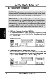
... no more than 46 cm (18 in.), with the red stripe to mini DIN adapter on the connectors. This connector will cause damage to your motherboard. Placing jumper caps over these connector pins will not allow standard AT size (large DIN) keyboard plugs. PS/2 Keyboard (6-pin female) 26 ASUS P4T-M User... is for connectors or power sources. H/W SETUP Connectors 2) PS/2 Keyboard Connector (Purple 6-pin PS2KBMS) This connection is detected. See PS/2 Mouse Function Control in the Motherboard Layout.
... no more than 46 cm (18 in.), with the red stripe to mini DIN adapter on the connectors. This connector will cause damage to your motherboard. Placing jumper caps over these connector pins will not allow standard AT size (large DIN) keyboard plugs. PS/2 Keyboard (6-pin female) 26 ASUS P4T-M User... is for connectors or power sources. H/W SETUP Connectors 2) PS/2 Keyboard Connector (Purple 6-pin PS2KBMS) This connection is detected. See PS/2 Mouse Function Control in the Motherboard Layout.


