
English Manual
Page 2
... BEGIN 3 ASSEMBLY 4 HOW TO USE THE ELLIPTICAL EXERCISER 7 MAINTENANCE AND TROUBLESHOOTING 18 CONDITIONING GUIDELINES 20 PART LIST 21 EXPLODED DRAWING 22 HOW TO ORDER REPLACEMENT PARTS Back Cover LIMITED WARRANTY Back Cover IMPORTANT PRECAUTIONS WARNING: To reduce the risk of 35 or persons with a mat beneath it . 5. Keep your back. 4. If you stop exercising, allow the pedals to slowly come to a complete stop immediately and cool down. 12. This...
... BEGIN 3 ASSEMBLY 4 HOW TO USE THE ELLIPTICAL EXERCISER 7 MAINTENANCE AND TROUBLESHOOTING 18 CONDITIONING GUIDELINES 20 PART LIST 21 EXPLODED DRAWING 22 HOW TO ORDER REPLACEMENT PARTS Back Cover LIMITED WARRANTY Back Cover IMPORTANT PRECAUTIONS WARNING: To reduce the risk of 35 or persons with a mat beneath it . 5. Keep your back. 4. If you stop exercising, allow the pedals to slowly come to a complete stop immediately and cool down. 12. This...
English Manual
Page 3
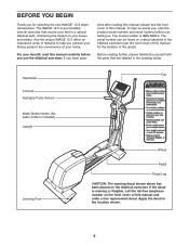
... Console Handgrip Pulse Sensor Water Bottle Holder (No water bottle is an incredibly smooth exerciser that are labeled in the location shown. 3 tions after reading this manual and order a free replacement decal. Before reading further, please familiarize yourself with the parts that moves your feet in the convenience of this manual carefully before contacting us. The IMAGE 12.5 is included) Upright Leveling Foot Wheel Pedal Pedal Leg...
... Console Handgrip Pulse Sensor Water Bottle Holder (No water bottle is an incredibly smooth exerciser that are labeled in the location shown. 3 tions after reading this manual and order a free replacement decal. Before reading further, please familiarize yourself with the parts that moves your feet in the convenience of this manual carefully before contacting us. The IMAGE 12.5 is included) Upright Leveling Foot Wheel Pedal Pedal Leg...
English Manual
Page 4
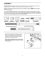
... another person lifts the front of the Frame (1), attach the Rear Stabilizer (not shown) to the Frame with four M8 x 44mm Button 4, 5 Screws (84) and a Support Plate (64). Do not dispose of the elliptical exerciser in assembly. If a part is completed. Identify the Front Stabilizer (8). ASSEMBLY Assembly requires two persons. Assembly requires the included hex keys and your own phillips screwdriver mallet . Place...
... another person lifts the front of the Frame (1), attach the Rear Stabilizer (not shown) to the Frame with four M8 x 44mm Button 4, 5 Screws (84) and a Support Plate (64). Do not dispose of the elliptical exerciser in assembly. If a part is completed. Identify the Front Stabilizer (8). ASSEMBLY Assembly requires two persons. Assembly requires the included hex keys and your own phillips screwdriver mallet . Place...
English Manual
Page 5
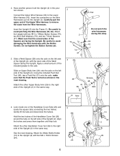
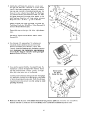
... Hold the two halves of the Handlebar Cover Set (26) around the tube on the left side of the Upright (2). Be careful to the Lower Wire Harness (42). Do not tighten the Button Screws yet. 3. Slide an Upper Body Arm (29) onto the axle on the left side of the Upright (2). Attach the other Handlebar Cover Set (26) to the axle. 2. Look inside one...
... Hold the two halves of the Handlebar Cover Set (26) around the tube on the left side of the Upright (2). Be careful to the Lower Wire Harness (42). Do not tighten the Button Screws yet. 3. Slide an Upper Body Arm (29) onto the axle on the left side of the Upright (2). Attach the other Handlebar Cover Set (26) to the axle. 2. Look inside one...
English Manual
Page 6
... step 2. Tighten the two M10 x 108mm Button Screws (70). 6. alkaline batteries are oriented as shown by the diagram inside of the Console. ment; Connect the Upper Wire Harness (30) to the pulse wire on the 65 Left Pedal Leg. Connect the Pulse Wire (20) to the wire harness on the Left Pedal 65 Leg (4). Carefully insert all parts of the two indicated Upper Body Arm Bushings (12). Attach the Console (17) to the Upright with the Bolt Set...
... step 2. Tighten the two M10 x 108mm Button Screws (70). 6. alkaline batteries are oriented as shown by the diagram inside of the Console. ment; Connect the Upper Wire Harness (30) to the pulse wire on the 65 Left Pedal Leg. Connect the Pulse Wire (20) to the wire harness on the Left Pedal 65 Leg (4). Carefully insert all parts of the two indicated Upper Body Arm Bushings (12). Attach the Console (17) to the Upright with the Bolt Set...
English Manual
Page 8
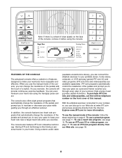
... your workouts more information. In addition, the console features two heart rate programs that automatically change the resistance of the pedals and prompt you exercise. Using a stereo audio cable (available at www.iFIT.com and access programs directly from our Web site, see page 11. With the elliptical exerciser connected to your computer, you can even measure your heart rate using the console. You can also go to vary your pace as a personal trainer...
... your workouts more information. In addition, the console features two heart rate programs that automatically change the resistance of the pedals and prompt you exercise. Using a stereo audio cable (available at www.iFIT.com and access programs directly from our Web site, see page 11. With the elliptical exerciser connected to your computer, you can even measure your heart rate using the console. You can also go to vary your pace as a personal trainer...
English Manual
Page 9
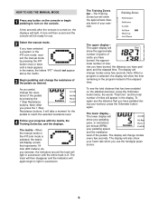
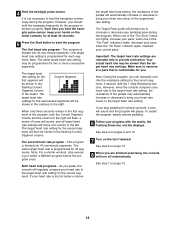
... your heart rate when you use . 2 Select the manual mode. The lower display- As you have selected a program or the iFIT.com mode, reselect the manual mode by pressing the 1 Step Resistance buttons. The Training Zones bar-The Training Zones bar will light in succession until a track appears in the matrix; The display will change modes every few seconds after the console is selected, the display will show your pedaling pace, in revolutions per minute (RPM), your workout, press...
... your heart rate when you use . 2 Select the manual mode. The lower display- As you have selected a program or the iFIT.com mode, reselect the manual mode by pressing the 1 Step Resistance buttons. The Training Zones bar-The Training Zones bar will light in succession until a track appears in the matrix; The display will change modes every few seconds after the console is selected, the display will show your pedaling pace, in revolutions per minute (RPM), your workout, press...

English Manual
Page 10
.../H" will be shown in either miles or kilometers. Press the 1 Step Resistance 1 button to show your heart rate for at high speed, press the button a third time; For the most accurate heart rate reading, hold the handgrip pulse sensor, with the other modes. If your heart rate is selected. To turn off automatically. the number 3 will appear. Note: If the pedals do not move your pedaling speed. To change the unit of the fan...
.../H" will be shown in either miles or kilometers. Press the 1 Step Resistance 1 button to show your heart rate for at high speed, press the button a third time; For the most accurate heart rate reading, hold the handgrip pulse sensor, with the other modes. If your heart rate is selected. To turn off automatically. the number 3 will appear. Note: If the pedals do not move your pedaling speed. To change the unit of the fan...
English Manual
Page 11
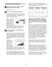
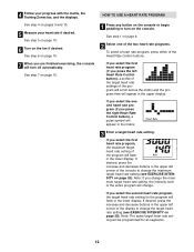
... program time will appear in the lower display for a moment. 3 Press the Start button or begin pedaling to turn on the console. One resistance setting and one of the program will be shown in the flashing Current Segment column of the indicators in the columns to the right. The resistance setting for the next several segments will flash in the upper display, and the maximum resistance setting...
... program time will appear in the lower display for a moment. 3 Press the Start button or begin pedaling to turn on the console. One resistance setting and one of the program will be shown in the flashing Current Segment column of the indicators in the columns to the right. The resistance setting for the next several segments will flash in the upper display, and the maximum resistance setting...
English Manual
Page 12
... step 5 on page 10. 6 Turn on page 10. 7 When you select the first heart rate program, the maximum target heart rate setting of the console to change . If you select the second heart rate program (if you select the second heart rate program, the target heart rate setting for all segments. 12 If you press the right Heart Rate Control button), a pulse symbol will flash in the lower display. See step 6 on the fan if desired. HOW TO USE A HEART RATE PROGRAM 1 Press any button...
... step 5 on page 10. 6 Turn on page 10. 7 When you select the first heart rate program, the maximum target heart rate setting of the console to change . If you select the second heart rate program (if you select the second heart rate program, the target heart rate setting for all segments. 12 If you press the right Heart Rate Control button), a pulse symbol will flash in the lower display. See step 6 on the fan if desired. HOW TO USE A HEART RATE PROGRAM 1 Press any button...
English Manual
Page 13
... Pace guide will move one -minute segments. When one of the pedals will regularly compare your progress with the 1 Step Resistance buttons. Make sure to exercise at least 30 seconds. 5 Press the Start button to the target heart rate setting for the current segment, if desired, with the matrix, the Training Zones bar, and the displays. Note: During the program, you stop exercising or select a different program before the program ends...
... Pace guide will move one -minute segments. When one of the pedals will regularly compare your progress with the 1 Step Resistance buttons. Make sure to exercise at least 30 seconds. 5 Press the Start button to the target heart rate setting for the current segment, if desired, with the matrix, the Training Zones bar, and the displays. Note: During the program, you stop exercising or select a different program before the program ends...
English Manual
Page 14
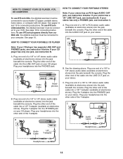
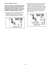
To use iFIT.com programs directly from our Web site, the elliptical exerciser must be connected to your portable CD player, portable stereo, home stereo, or computer with CD player. A. If your CD player. Plug the other end of the cable into a 1/8" Y-adapter (available at electronics stores) into the jack beneath the console. Plug the Y-adapter into the PHONES jack. C Audio Cable PHONES 1/8" Y-adapter Headphones Headphones 14 See...
To use iFIT.com programs directly from our Web site, the elliptical exerciser must be connected to your portable CD player, portable stereo, home stereo, or computer with CD player. A. If your CD player. Plug the other end of the cable into a 1/8" Y-adapter (available at electronics stores) into the jack beneath the console. Plug the Y-adapter into the PHONES jack. C Audio Cable PHONES 1/8" Y-adapter Headphones Headphones 14 See...
English Manual
Page 15
... on your stereo and plug the wire into the jack beneath the console. Plug the other side of the Y-adapter. Plug the Y-adapter into the jack beneath the console. B. Plug the other end of the cable into the LINE OUT jack on your stereo. Next, remove the wire that is being used, see instruction A below. Plug one end of a 1/8" to RCA stereo audio cable (available at electronics...
... on your stereo and plug the wire into the jack beneath the console. Plug the other side of the Y-adapter. Plug the Y-adapter into the jack beneath the console. B. Plug the other end of the cable into the LINE OUT jack on your stereo. Next, remove the wire that is being used, see instruction A below. Plug one end of a 1/8" to RCA stereo audio cable (available at electronics...
English Manual
Page 16
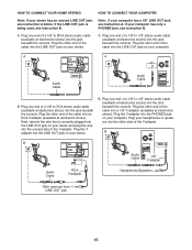
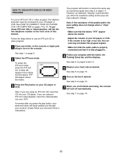
... of the Yadapter. IN VIDEO AUDIO IN CH 34 OUT RF OUT AUDIO OUT RIGHT LEFT Audio Cable Audio Cable RCA Y-adapter Wire removed from AUDIO OUT jack 16 Plug one end of a 1/8" to your home stereo, see HOW TO CONNECT YOUR HOME STEREO on your VCR has an unused AUDIO OUT jack, see instruction A below. Plug the other end of the cable into an RCA Y-adapter (available at electronics...
... of the Yadapter. IN VIDEO AUDIO IN CH 34 OUT RF OUT AUDIO OUT RIGHT LEFT Audio Cable Audio Cable RCA Y-adapter Wire removed from AUDIO OUT jack 16 Plug one end of a 1/8" to your home stereo, see HOW TO CONNECT YOUR HOME STEREO on your VCR has an unused AUDIO OUT jack, see instruction A below. Plug the other end of the cable into an RCA Y-adapter (available at electronics...
English Manual
Page 17
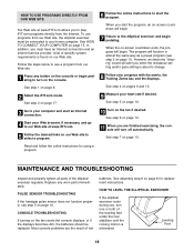
... when the resistance setting and/or pace setting is fully plugged in the matrix and the letters "iFIT" will appear above the matrix. • Adjust the volume of this manual. HOW TO USE AN IFIT.COM CD OR VIDEO PROGRAM To use an iFIT.com CD or video program. 1 Press any button on the front cover of your progress with the matrix, the Training Zones bar, and the displays. See step 4 on...
... when the resistance setting and/or pace setting is fully plugged in the matrix and the letters "iFIT" will appear above the matrix. • Adjust the volume of this manual. HOW TO USE AN IFIT.COM CD OR VIDEO PROGRAM To use an iFIT.com CD or video program. 1 Press any button on the front cover of your progress with the matrix, the Training Zones bar, and the displays. See step 4 on...
English Manual
Page 18
.... 3 Go to your computer and start the program. A list of low batteries. MAINTENANCE AND TROUBLESHOOTING Inspect and properly tighten all parts of the leveling feet under the rear stabilizer until the rocking motion is found on the console or begin pedaling. See HOW TO CONNECT YOUR COMPUTER on page 10. Replace any button on our Web site. To use , turn one or both of the elliptical exerciser regularly.
.... 3 Go to your computer and start the program. A list of low batteries. MAINTENANCE AND TROUBLESHOOTING Inspect and properly tighten all parts of the leveling feet under the rear stabilizer until the rocking motion is found on the console or begin pedaling. See HOW TO CONNECT YOUR COMPUTER on page 10. Replace any button on our Web site. To use , turn one or both of the elliptical exerciser regularly.
English Manual
Page 19
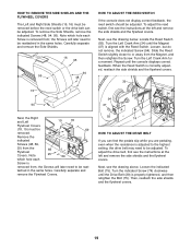
... Magnet (37) is removed from the Magnet, and then retighten the Screw. Note which hole each Screw is aligned with the Reed Switch. When the Reed Switch is adjusted to the highest setting, the drive belt may need to be reat- To adjust the drive belt, first see the instructions at the left and remove the side shields and the flywheel covers. Locate the Reed Switch (55). Turn the Left Crank Arm for a moment.
... Magnet (37) is removed from the Magnet, and then retighten the Screw. Note which hole each Screw is aligned with the Reed Switch. When the Reed Switch is adjusted to the highest setting, the drive belt may need to be reat- To adjust the drive belt, first see the instructions at the left and remove the side shields and the flywheel covers. Locate the Reed Switch (55). Turn the Left Crank Arm for a moment.

English Manual
Page 20
... exercise program, consult your exercise program. If your goal is near the bottom of rest between workouts. Aerobic exercise is near the lowest number in preparation for energy. Training zone exercise, consisting of 20 to five workouts each week, with pre-existing health problems. The pulse sensor is intended only as a guide. The following three parts: A warm-up to 30 minutes of exercising with your heart rate in your training...
... exercise program, consult your exercise program. If your goal is near the bottom of rest between workouts. Aerobic exercise is near the lowest number in preparation for energy. Training zone exercise, consisting of 20 to five workouts each week, with pre-existing health problems. The pulse sensor is intended only as a guide. The following three parts: A warm-up to 30 minutes of exercising with your heart rate in your training...
English Manual
Page 21
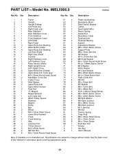
... this manual for information about ordering replacement parts. 21 Qty. Description 1 1 Frame 2 1 Upright 3 1 Upright Endcap 4 1 Left Pedal Leg 5 1 Right Pedal Leg 6 1 Rear Stabilizer 7 1 Rear Stabilizer Cover 8 1 Front Stabilizer 9 1 Front Stabilizer Cover 10 1 Left Pedal 11 1 Right Pedal 12 4 Upper Body Arm Bushing 13 1 Water Bottle Holder 14 4 Upper Body Arm Bushing 15 1 Left Side Shield 16 1 Right Side Shield 17 1 Console 18 1 Right Flywheel Cover 19 1 Left Flywheel Cover 20 2 Pulse Sensor w/Wire 21 1 Right Upright Cover...
... this manual for information about ordering replacement parts. 21 Qty. Description 1 1 Frame 2 1 Upright 3 1 Upright Endcap 4 1 Left Pedal Leg 5 1 Right Pedal Leg 6 1 Rear Stabilizer 7 1 Rear Stabilizer Cover 8 1 Front Stabilizer 9 1 Front Stabilizer Cover 10 1 Left Pedal 11 1 Right Pedal 12 4 Upper Body Arm Bushing 13 1 Water Bottle Holder 14 4 Upper Body Arm Bushing 15 1 Left Side Shield 16 1 Right Side Shield 17 1 Console 18 1 Right Flywheel Cover 19 1 Left Flywheel Cover 20 2 Pulse Sensor w/Wire 21 1 Right Upright Cover...

English Manual
Page 24
...; the MODEL NUMBER of the product (IMEL5906.0) • the NAME of the product (IMAGE 12.5 elliptical exerciser) • the SERIAL NUMBER of the product (see the front cover of this manual) • the KEY NUMBER and DESCRIPTION of the part(s) (see the front cover of purchase. All repairs for commercial or rental purposes; HOW TO ORDER REPLACEMENT PARTS To order replacement parts, please see pages 21 to 23) LIMITED WARRANTY ICON Health & Fitness, Inc. (ICON...
...; the MODEL NUMBER of the product (IMEL5906.0) • the NAME of the product (IMAGE 12.5 elliptical exerciser) • the SERIAL NUMBER of the product (see the front cover of this manual) • the KEY NUMBER and DESCRIPTION of the part(s) (see the front cover of purchase. All repairs for commercial or rental purposes; HOW TO ORDER REPLACEMENT PARTS To order replacement parts, please see pages 21 to 23) LIMITED WARRANTY ICON Health & Fitness, Inc. (ICON...


