

Instruction Manual
Page 3
...23- 28 s Operation 23 s Mode select function 25 s Specifying skip channel and frequency 25 s Automatic bank limit/skip functions 26 s Voice scan control function 26 s Programming scan edge frequencies 27 s Scan speed/delay functions 27 7 SLEEP TIMER 29 8 SET MODE 30 s General 30 s Quick set... mode items 31 s Initial set mode items 31 9 CONNECTOR INFORMATION 33- 34 10 CONTROL COMMANDS 35- 36 s Command table 35 s Data format 35 11 MAINTENANCE 37 s Disassembly 37 s Fuse replacement 37 s Level adjustments 37 s Memory ...
...23- 28 s Operation 23 s Mode select function 25 s Specifying skip channel and frequency 25 s Automatic bank limit/skip functions 26 s Voice scan control function 26 s Programming scan edge frequencies 27 s Scan speed/delay functions 27 7 SLEEP TIMER 29 8 SET MODE 30 s General 30 s Quick set... mode items 31 s Initial set mode items 31 9 CONNECTOR INFORMATION 33- 34 10 CONTROL COMMANDS 35- 36 s Command table 35 s Data format 35 11 MAINTENANCE 37 s Disassembly 37 s Fuse replacement 37 s Level adjustments 37 s Memory ...
Instruction Manual
Page 4
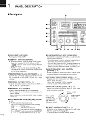
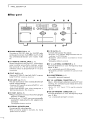
r8500 COMMUNICATION RECEIVER FM SLEEP LOCK NB AFC AGC-F APF-N RECV 10-ATT-20 BANK ICOM I REC REMOTE MODE e WFM FM ... signal). 1 PANEL DESCRIPTION s Front panel @0 q POWER w SLEEP/ SET S 1 3 5 7 9 +20dB +60dB SIGNAL iC- to enter quick set . ¯ Push for removing pulse-type noise when SSB, CW or AM mode is selected (p. 15). • ...SSB, CW, WFM and AM narrow modes) • Signals below the S-meter level are muted. !1 IF SHIFT CONTROL [IF SHIFT] (p. 14) Shifts the center frequency of a tape recorder for 1 sec. Connects to increase the audio...
r8500 COMMUNICATION RECEIVER FM SLEEP LOCK NB AFC AGC-F APF-N RECV 10-ATT-20 BANK ICOM I REC REMOTE MODE e WFM FM ... signal). 1 PANEL DESCRIPTION s Front panel @0 q POWER w SLEEP/ SET S 1 3 5 7 9 +20dB +60dB SIGNAL iC- to enter quick set . ¯ Push for removing pulse-type noise when SSB, CW or AM mode is selected (p. 15). • ...SSB, CW, WFM and AM narrow modes) • Signals below the S-meter level are muted. !1 IF SHIFT CONTROL [IF SHIFT] (p. 14) Shifts the center frequency of a tape recorder for 1 sec. Connects to increase the audio...
Instruction Manual
Page 5
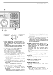
...toggle the audio peak filter circuit ON and OFF. • Use the [APF] control to adjust the center of the audio !7 MAIN DIAL Changes the operating frequency, set mode !2 AUDIO PEAK FILTER CONTROL [APF] (p. 15) Adjusts the audio peak filter setting to cover both the ... rotation adjusts the filter setting lower. and narrow. • 'Narrow' is available for 1 sec. 1 PANEL DESCRIPTION !9 ∞ OFF DLY kHz SEL-CH SKIP-CH IC-R8500 M 1 QZ 4 GHI 2 ABC 5 JKL 3 DEF 6 MNO . ; , M-CH BANK 7 PRS . 8 TUV 0 9 WXY CE NAME BANK ENT ENT MEMO SEL PROG AUTO SCAN...
...toggle the audio peak filter circuit ON and OFF. • Use the [APF] control to adjust the center of the audio !7 MAIN DIAL Changes the operating frequency, set mode !2 AUDIO PEAK FILTER CONTROL [APF] (p. 15) Adjusts the audio peak filter setting to cover both the ... rotation adjusts the filter setting lower. and narrow. • 'Narrow' is available for 1 sec. 1 PANEL DESCRIPTION !9 ∞ OFF DLY kHz SEL-CH SKIP-CH IC-R8500 M 1 QZ 4 GHI 2 ABC 5 JKL 3 DEF 6 MNO . ; , M-CH BANK 7 PRS . 8 TUV 0 9 WXY CE NAME BANK ENT ENT MEMO SEL PROG AUTO SCAN...
Instruction Manual
Page 6
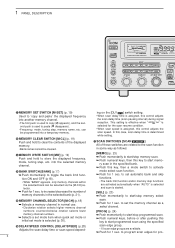
... scan. ¯ Push numeral keys, then this case, scan delay time is selected (p. 30). @6 DELAY/SPEED CONTROL [DELAY/SPEED] (p.28) Adjusts the scan delay time or scan speed depend- [MEMO] (p. 23) ¯ Push... start memo- 1 PANEL DESCRIPTION POWER SLEEP/ SET REC REMOTE REC OUT PHONES S 1 3 5 7 9 +20dB +60dB SIGNAL iC- ing on the [DLY D/S ] switch setting. • When scan delay time is started. [SEL] (p. 23) ¯...CH] selector. ¯ Push for 1 sec. r8500 COMMUNICATION RECEIVER FM SLEEP LOCK NB AFC AGC-F APF-N RECV 10-ATT-20 BANK ICOM WFM MODE FM AM SSB/CW NB/AFC AF...
... scan. ¯ Push numeral keys, then this case, scan delay time is selected (p. 30). @6 DELAY/SPEED CONTROL [DELAY/SPEED] (p.28) Adjusts the scan delay time or scan speed depend- [MEMO] (p. 23) ¯ Push... start memo- 1 PANEL DESCRIPTION POWER SLEEP/ SET REC REMOTE REC OUT PHONES S 1 3 5 7 9 +20dB +60dB SIGNAL iC- ing on the [DLY D/S ] switch setting. • When scan delay time is started. [SEL] (p. 23) ¯...CH] selector. ¯ Push for 1 sec. r8500 COMMUNICATION RECEIVER FM SLEEP LOCK NB AFC AGC-F APF-N RECV 10-ATT-20 BANK ICOM WFM MODE FM AM SSB/CW NB/AFC AF...
Instruction Manual
Page 7
...• The VSC function resumes the scan when a detected signal does not contain voice components. • "VSC" appears while the voice scan control function is activated. [PRIO] (p. 25) ¯ Push momentarily to start/stop priority scan. • Priority scan can be used for several.../scan speed setting condition. • The function of the [DELAY/SPEED] control can be selected. @8 KEYPAD The keypad can be used in combination with the [MEMO] switch. ¯ Push for 1 sec. 1 PANEL DESCRIPTION ∞ OFF DLY kHz SEL-CH SKIP-CH IC-R8500 M 1 QZ 2 ABC 3 DEF . ; , M-CH 4 GHI 5...
...• The VSC function resumes the scan when a detected signal does not contain voice components. • "VSC" appears while the voice scan control function is activated. [PRIO] (p. 25) ¯ Push momentarily to start/stop priority scan. • Priority scan can be used for several.../scan speed setting condition. • The function of the [DELAY/SPEED] control can be selected. @8 KEYPAD The keypad can be used in combination with the [MEMO] switch. ¯ Push for 1 sec. 1 PANEL DESCRIPTION ∞ OFF DLY kHz SEL-CH SKIP-CH IC-R8500 M 1 QZ 2 ABC 3 DEF . ; , M-CH 4 GHI 5...
Instruction Manual
Page 8
... Connects an antenna to a PC with some versions. An RS-232C cable can be used to connect the IC-R8500 to the DC 13.8 V jack. *Not supplied with several receivers for command control via the PC. u DC IN JACK (p. 8) Connects the supplied* AC adapter. • A regulator ...circuit has been designed between this connector (p. 31). !1 VHF/UHF ANTENNA CONNECTOR (p. 8) Connects an antenna to an Icom CI-V system transceiver or another receiver for...
... Connects an antenna to a PC with some versions. An RS-232C cable can be used to connect the IC-R8500 to the DC 13.8 V jack. *Not supplied with several receivers for command control via the PC. u DC IN JACK (p. 8) Connects the supplied* AC adapter. • A regulator ...circuit has been designed between this connector (p. 31). !1 VHF/UHF ANTENNA CONNECTOR (p. 8) Connects an antenna to an Icom CI-V system transceiver or another receiver for...

Instruction Manual
Page 9
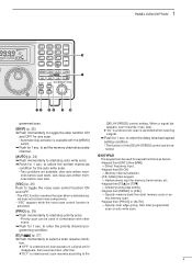
... BLANKER INDICATOR (p. 15) Appears when the noise blanker circuit is selected. t VSC INDICATOR (p. 26) Appears when the voice scan control function is rotated. no indication appears when AGC slow is selected. !9 RECEIVE INDICATOR Appears while receiving. @0 FM CENTER INDICATORS (p....appears when the audio peak filter function is activated. !7 ATTENUATOR INDICATORS Appear when the RF attenuator is activated. !8 AUTOMATIC GAIN CONTROL INDICATOR (p. 15) AGC-F appears when AGC fast is selected; Display names programmed into another memory channel. !2 SELECT CHANNEL INDICATOR (p. 23...
... BLANKER INDICATOR (p. 15) Appears when the noise blanker circuit is selected. t VSC INDICATOR (p. 26) Appears when the voice scan control function is rotated. no indication appears when AGC slow is selected. !9 RECEIVE INDICATOR Appears while receiving. @0 FM CENTER INDICATORS (p....appears when the audio peak filter function is activated. !7 ATTENUATOR INDICATORS Appear when the RF attenuator is activated. !8 AUTOMATIC GAIN CONTROL INDICATOR (p. 15) AGC-F appears when AGC fast is selected; Display names programmed into another memory channel. !2 SELECT CHANNEL INDICATOR (p. 23...
Instruction Manual
Page 11
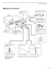
...] jack. AC adapter AD-55/A/V Computer control (p. 10) TV adapter or high speed data connection (pgs. 16, 40) The jumper plug must be connected to 1.3 GHz coverage. 0.1-30 MHz coverage 0.1-30 MHz coverage Select the active antenna connector in quick set mode (p. 31) 8 2 CONNECTIONS s Required connections IC-R8500 External speaker (p. 44) Connect either...
...] jack. AC adapter AD-55/A/V Computer control (p. 10) TV adapter or high speed data connection (pgs. 16, 40) The jumper plug must be connected to 1.3 GHz coverage. 0.1-30 MHz coverage 0.1-30 MHz coverage Select the active antenna connector in quick set mode (p. 31) 8 2 CONNECTIONS s Required connections IC-R8500 External speaker (p. 44) Connect either...

Instruction Manual
Page 13
... the control command table. RS-232C cable Personal computer A DB9/DB25 adapter may be required depending on the PC's connector. s Transceive function Icom CI-V transceivers or receivers can connect directly to other audio equipment. See pgs. 35, 36 for one of multiple functions such as instant frequency/name programming using appropriate software. IC-R8500...
... the control command table. RS-232C cable Personal computer A DB9/DB25 adapter may be required depending on the PC's connector. s Transceive function Icom CI-V transceivers or receivers can connect directly to other audio equipment. See pgs. 35, 36 for one of multiple functions such as instant frequency/name programming using appropriate software. IC-R8500...
Instruction Manual
Page 16
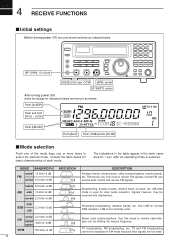
... signals. 4 RECEIVE FUNCTIONS s Initial settings Before turning power ON, set controls and switches as follows: Push [SLEEP] Push and hold [SPCH • LOCK] Push [NB/AFC] FM SLEEP LOCK NB AFC AGC-F APF-N RECV 10-ATT-20 BANK *ICOM ∞ OFF DLY kHz IC-R8500 Push [AGC] Push [10dB] and/or [20 dB] s Mode...
... signals. 4 RECEIVE FUNCTIONS s Initial settings Before turning power ON, set controls and switches as follows: Push [SLEEP] Push and hold [SPCH • LOCK] Push [NB/AFC] FM SLEEP LOCK NB AFC AGC-F APF-N RECV 10-ATT-20 BANK *ICOM ∞ OFF DLY kHz IC-R8500 Push [AGC] Push [10dB] and/or [20 dB] s Mode...
Instruction Manual
Page 17
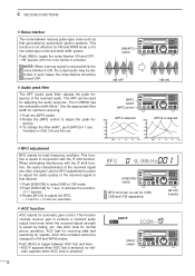
... the tuning when a receive frequency drifts or goes off -center frequency is received, the frequency in use. Set the shift control to reflect the center of these indicators appears when the received signal is rotated past center, the S-meter shows the signal strength... of squelch, noise squelch and S-meter squelch. AFC RECV When one of the off-center indicators appears, the IC-R8500 can be tuned off -center. 4 RECEIVE FUNCTIONS s Squelch function The IC-R8500 has 2 types of weak signals. Strong signals exceeding a certain level will open for reception of the IF (...
... the tuning when a receive frequency drifts or goes off -center frequency is received, the frequency in use. Set the shift control to reflect the center of these indicators appears when the received signal is rotated past center, the S-meter shows the signal strength... of squelch, noise squelch and S-meter squelch. AFC RECV When one of the off-center indicators appears, the IC-R8500 can be tuned off -center. 4 RECEIVE FUNCTIONS s Squelch function The IC-R8500 has 2 types of weak signals. Strong signals exceeding a certain level will open for reception of the IF (...
Instruction Manual
Page 18
...IC-R8500 has two selectable width filters.* Use the appropriate filter width for 1 sec. to activate the function. • BFO appears. Ž Rotate [M-CH] to adjust the BFO. • -1.2 kHz to adjust the peak fre- D BFO adjustment BFO stands for automatic gain control...CW] for optimum receiving. Œ Push the [APF] switch. Rotate the [APF] control to +1.2 kHz are often changed in conjunction with the IF shift function, the audio characteristics of ... AGC-F RECV ICOM- [AGC] SCAN SET switch 15 In such cases, the noise blanker should be distorted....
...IC-R8500 has two selectable width filters.* Use the appropriate filter width for 1 sec. to activate the function. • BFO appears. Ž Rotate [M-CH] to adjust the BFO. • -1.2 kHz to adjust the peak fre- D BFO adjustment BFO stands for automatic gain control...CW] for optimum receiving. Œ Push the [APF] switch. Rotate the [APF] control to +1.2 kHz are often changed in conjunction with the IF shift function, the audio characteristics of ... AGC-F RECV ICOM- [AGC] SCAN SET switch 15 In such cases, the noise blanker should be distorted....
Instruction Manual
Page 20
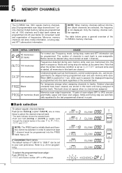
...The table below gives a general overview of the selected bank. Note that when the written memories condition is set as from beacons, control-coded signals, etc., can be programmed into the FREE bank. while scan is paused, the displayed frequency is started, all 1000 ...Mode and tuning step are written at least 1 channel). Convenient: Bank names The default names of frequencies. 5 MEMORY CHANNELS s General The IC-R8500 has 1000 regular memory channels, plus 20 programmable scan edge channels and 1 priority channel. 8-digit memory names are programmed into all memories in ...
...The table below gives a general overview of the selected bank. Note that when the written memories condition is set as from beacons, control-coded signals, etc., can be programmed into the FREE bank. while scan is paused, the displayed frequency is started, all 1000 ...Mode and tuning step are written at least 1 channel). Convenient: Bank names The default names of frequencies. 5 MEMORY CHANNELS s General The IC-R8500 has 1000 regular memory channels, plus 20 programmable scan edge channels and 1 priority channel. 8-digit memory names are programmed into all memories in ...
Instruction Manual
Page 24
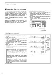
... Delete memory channels from banks that if there is only one channel in a bank, it cannot be moved to the 'free' bank. [BANK] switch [M-CH] control BANK USR-T BLANK BANK USR-T INS. 1CH BANK USR-T DEL. 1CH BANK USR-T BLANK The number of "INS. 1CH," "DEL. 1CH," "ADD.10CH," or.... This means that have more than one at a time to prevent accidental deletion of banks cannot be decreased. 5 MEMORY CHANNELS s Assigning channel numbers The IC-R8500 has 20 banks in which you want to add channels. • Channels added to a bank are deleted from or added (inserted) to banks to suit...
... Delete memory channels from banks that if there is only one channel in a bank, it cannot be moved to the 'free' bank. [BANK] switch [M-CH] control BANK USR-T BLANK BANK USR-T INS. 1CH BANK USR-T DEL. 1CH BANK USR-T BLANK The number of "INS. 1CH," "DEL. 1CH," "ADD.10CH," or.... This means that have more than one at a time to prevent accidental deletion of banks cannot be decreased. 5 MEMORY CHANNELS s Assigning channel numbers The IC-R8500 has 20 banks in which you want to add channels. • Channels added to a bank are deleted from or added (inserted) to banks to suit...

Instruction Manual
Page 26
...CH • BANKv] or [ENT • BANKw] to select the desired bank. • Direct selection is also available as below. Set the [SQUELCH] control to the threshold point. Ž Push [MEMO] to start scan. • "SEL" appears in the bank name area. Push [SEL] again to specify...scan. Bank selection during memory scan-The selected bank can be changed without using [M-CH • BANKv] or [ENT • BANKw]. Set the squelch control to the threshold point. Ž Push [SEL] momentarily to start the scan. • "MEMO" appears in the bank name area. Push [MEMO...
...CH • BANKv] or [ENT • BANKw] to select the desired bank. • Direct selection is also available as below. Set the [SQUELCH] control to the threshold point. Ž Push [MEMO] to start scan. • "SEL" appears in the bank name area. Push [SEL] again to specify...scan. Bank selection during memory scan-The selected bank can be changed without using [M-CH • BANKv] or [ENT • BANKw]. Set the squelch control to the threshold point. Ž Push [SEL] momentarily to start the scan. • "MEMO" appears in the bank name area. Push [MEMO...
Instruction Manual
Page 27
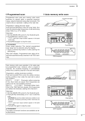
... Push [AUTO] momentarily or for 1 sec. Preparation-written memories condition: Push and hold [PROG] to stop : Œ Set the [SQUELCH] control to the threshold point. Push [PROG] to start the scan. • CAUTION: Be sure the written memories condition is automatically written into a... way as skip channels in the bank name area. Ž Push [AUTO] again to stop : Œ Set the [SQUELCH] control to select the condition. Convenient: The same convenient functions are available as desired, otherwise previously written memories are written into channels, starting from channel...
... Push [AUTO] momentarily or for 1 sec. Preparation-written memories condition: Push and hold [PROG] to stop : Œ Set the [SQUELCH] control to the threshold point. Push [PROG] to start the scan. • CAUTION: Be sure the written memories condition is automatically written into a... way as skip channels in the bank name area. Ž Push [AUTO] again to stop : Œ Set the [SQUELCH] control to select the condition. Convenient: The same convenient functions are available as desired, otherwise previously written memories are written into channels, starting from channel...

Instruction Manual
Page 29
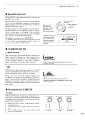
... AUTO or MANUAL. Push [MEMO] to return to "OFF" or " ". IC-R8500 Unmodulated signal Scan edge 1 Modulated signal Scan edge 2 Scan Skip Scan pauses or is useful when you don't want unmodulated signals pausing or cancelling a scan. s Voice scan control function This function is cancelled. 26 the frequencies which are not checked... AUTO The skip function is turned ON automatically at scan start . [BANK] does not function during scan. VSC appears FM ∞ VSC OFF DLY kHz ICOM-
... AUTO or MANUAL. Push [MEMO] to return to "OFF" or " ". IC-R8500 Unmodulated signal Scan edge 1 Modulated signal Scan edge 2 Scan Skip Scan pauses or is useful when you don't want unmodulated signals pausing or cancelling a scan. s Voice scan control function This function is cancelled. 26 the frequencies which are not checked... AUTO The skip function is turned ON automatically at scan start . [BANK] does not function during scan. VSC appears FM ∞ VSC OFF DLY kHz ICOM-

Instruction Manual
Page 31
...:SPD DLY= 3S Toggle via the main dial Adjustable via the [M-CH] selector VR:DLY SPD=MAX Scan delay is assigned to the [DELAY/SPEED] control D Scan speed When scan speed is assigned to suit your operating style. Œ Push [DLY D/S ] for 1 sec. DELAY Longest delay time: 18 sec. SPEED Lowest... scan speed: 1 ch/sec. to 18 sec. When scan delay time is assigned to the [DELAY/SPEED] control, the scan speed is determined while "VR:SPD DLY: 3S" appears. • Rotate the [M-CH] selector to set value of 3 to enter the setting con...
...:SPD DLY= 3S Toggle via the main dial Adjustable via the [M-CH] selector VR:DLY SPD=MAX Scan delay is assigned to the [DELAY/SPEED] control D Scan speed When scan speed is assigned to suit your operating style. Œ Push [DLY D/S ] for 1 sec. DELAY Longest delay time: 18 sec. SPEED Lowest... scan speed: 1 ch/sec. to 18 sec. When scan delay time is assigned to the [DELAY/SPEED] control, the scan speed is determined while "VR:SPD DLY: 3S" appears. • Rotate the [M-CH] selector to set value of 3 to enter the setting con...

Instruction Manual
Page 33
...turn power ON. • Initial set mode is used for programming infrequently changed values or conditions of its items appears. Ž Rotate the [M-CH] control to select the desired item. Rotate the main dial to set the values or conditions for items) [DISPLAY EXAMPLE: INITIAL SET MODE] ON ...; Push [POWER] to turn power OFF. While pushing [SLEEP/ SET ] push [POWER] to set other switch will also exit quick set mode. The IC-R8500 has 2 separate set modes: quick set mode and initial set mode are now effective. 8 SET MODE Main dial (for contents) SCAN SET [SLEEP/ SET ] (...
...turn power ON. • Initial set mode is used for programming infrequently changed values or conditions of its items appears. Ž Rotate the [M-CH] control to select the desired item. Rotate the main dial to set the values or conditions for items) [DISPLAY EXAMPLE: INITIAL SET MODE] ON ...; Push [POWER] to turn power OFF. While pushing [SLEEP/ SET ] push [POWER] to set other switch will also exit quick set mode. The IC-R8500 has 2 separate set modes: quick set mode and initial set mode are now effective. 8 SET MODE Main dial (for contents) SCAN SET [SLEEP/ SET ] (...
Instruction Manual
Page 35
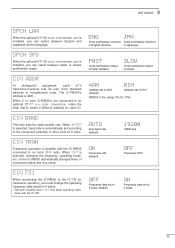
... 4 bytes. • This item must be set to an Icom CI-V radio. SET MODE 8 SPCH LAN When the optional UT-102 VOICE SYNTHESIZER UNIT is selected, changing the frequency, operating mode, etc. When 2 or more IC-R8500's are connected to an optional CT-17 CI-V LEVEL CONVERTER, ...731 When connecting the IC-R8500 to the IC-735 for each CI-V transceiver/receiver has its own Icom standard address in the range 01H to 5 bytes (default). SLOW Voice synthesizer output is automatically set to 7FH. Address set to the connected controller or other Icom CI-V radio. R8500 in hexadecimal code. OFF...
... 4 bytes. • This item must be set to an Icom CI-V radio. SET MODE 8 SPCH LAN When the optional UT-102 VOICE SYNTHESIZER UNIT is selected, changing the frequency, operating mode, etc. When 2 or more IC-R8500's are connected to an optional CT-17 CI-V LEVEL CONVERTER, ...731 When connecting the IC-R8500 to the IC-735 for each CI-V transceiver/receiver has its own Icom standard address in the range 01H to 5 bytes (default). SLOW Voice synthesizer output is automatically set to 7FH. Address set to the connected controller or other Icom CI-V radio. R8500 in hexadecimal code. OFF...
