
Instruction Manual
Page 2
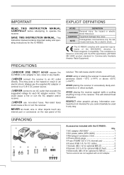
... shock. This will cause electric shock. Information overheard but not intended for you cannot lawfully be used in areas with the IC-R8500: Qty. Œ AC adapter (AD-55A 1 DC power cable (OPC-023C 1 Ž Mini plug (2-conductor, 3.5d 1 Phono (RCA) plugs 2 Fuse (FGMB 125...Equipment damage may occur. This compliance is based on conformity with an AC adapter. NEVER expose the IC-R8500 or AC adapter to rain, snow or any way. RNEVER use 1 ‘ Fuses (FGB 3 A; for DC cable 2 ’ Screws (M4 × 12 for optional MB-23 2 “ Screws (...
... shock. This will cause electric shock. Information overheard but not intended for you cannot lawfully be used in areas with the IC-R8500: Qty. Œ AC adapter (AD-55A 1 DC power cable (OPC-023C 1 Ž Mini plug (2-conductor, 3.5d 1 Phono (RCA) plugs 2 Fuse (FGMB 125...Equipment damage may occur. This compliance is based on conformity with an AC adapter. NEVER expose the IC-R8500 or AC adapter to rain, snow or any way. RNEVER use 1 ‘ Fuses (FGB 3 A; for DC cable 2 ’ Screws (M4 × 12 for optional MB-23 2 “ Screws (...
Instruction Manual
Page 8
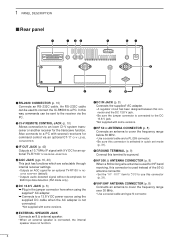
... a PL-259 connector. • Be sure this connector is used for HF band receiving, this way commands can be sent to an Icom CI-V system transceiver or another receiver for 9600 bps data detection (FM mode only). o GROUND TERMINAL (p. 9) Connect this terminal to a ground. !0 HF 500 Ω ... and the DC 13.8 V jack. • Be sure the jumper connector is not connected. *Not supplied with some versions. An RS-232C cable can be used to connect the IC-R8500 to a PC with 9 V DC for command control via the PC. e IF OUT JACK (p. 40) Outputs a 10.7 MHz IF signal with several ...
... a PL-259 connector. • Be sure this connector is used for HF band receiving, this way commands can be sent to an Icom CI-V system transceiver or another receiver for 9600 bps data detection (FM mode only). o GROUND TERMINAL (p. 9) Connect this terminal to a ground. !0 HF 500 Ω ... and the DC 13.8 V jack. • Be sure the jumper connector is not connected. *Not supplied with some versions. An RS-232C cable can be used to connect the IC-R8500 to a PC with 9 V DC for command control via the PC. e IF OUT JACK (p. 40) Outputs a 10.7 MHz IF signal with several ...
Instruction Manual
Page 11
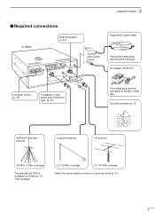
... antenna HF antenna 30 MHz -2 GHz coverage The optional AH-7000 is available for 25 MHz to the [DC 13.8V] jack. 2 CONNECTIONS s Required connections IC-R8500 External speaker (p. 44) Connect either power source Supplied DC power cable Unplug the jumper plug from the [DC13.8V] jack.
... antenna HF antenna 30 MHz -2 GHz coverage The optional AH-7000 is available for 25 MHz to the [DC 13.8V] jack. 2 CONNECTIONS s Required connections IC-R8500 External speaker (p. 44) Connect either power source Supplied DC power cable Unplug the jumper plug from the [DC13.8V] jack.
Instruction Manual
Page 12
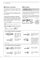
... cut the end of a 50 Ω matched antenna, use a gas pipe or electri- For best results, connect a heavy gauge cable to the IC-R8500 will result in ) 9 Screw the coupling ring onto the connector body. Make the distance between the [GND] terminal and ground as short ... the center conductor pin and No space solder it . 10 mm Soft Strip the cable as possible. PL-259 CONNECTOR INSTALLATION EXAMPLE Œ 30 mm Slide the coupling ring Ž down. The IC-R8500 requires at least 10 m, 33 ft) and select the active connector as follows: Œ ...
... cut the end of a 50 Ω matched antenna, use a gas pipe or electri- For best results, connect a heavy gauge cable to the IC-R8500 will result in ) 9 Screw the coupling ring onto the connector body. Make the distance between the [GND] terminal and ground as short ... the center conductor pin and No space solder it . 10 mm Soft Strip the cable as possible. PL-259 CONNECTOR INSTALLATION EXAMPLE Œ 30 mm Slide the coupling ring Ž down. The IC-R8500 requires at least 10 m, 33 ft) and select the active connector as follows: Œ ...

Instruction Manual
Page 13
... a control terminal, this jack can be recorded. RS-232C cable Personal computer A DB9/DB25 adapter may be connected via the [REMOTE] jack. s Data demodulation terminal See p. 16 for connection to a PC The IC-R8500 can be used for one of multiple functions such as instant ...radio is received and squelch opens. s Connecting to other audio equipment. IC-R8500 [AUX IN] or [LIVE IN] jack [REC REMOTE] jack: Grounds when a signal is changed. * When a set mode (p. 32). s Transceive function Icom CI-V transceivers or receivers can be required depending on the PC's connector...
... a control terminal, this jack can be recorded. RS-232C cable Personal computer A DB9/DB25 adapter may be connected via the [REMOTE] jack. s Data demodulation terminal See p. 16 for connection to a PC The IC-R8500 can be used for one of multiple functions such as instant ...radio is received and squelch opens. s Connecting to other audio equipment. IC-R8500 [AUX IN] or [LIVE IN] jack [REC REMOTE] jack: Grounds when a signal is changed. * When a set mode (p. 32). s Transceive function Icom CI-V transceivers or receivers can be required depending on the PC's connector...

Instruction Manual
Page 40
... solvents such as memory contents, set mode contents, etc. 11 MAINTENANCE s Disassembly For internal maintenance and optional installations, disassemble the receiver. Speaker cable s Fuse replacement If a fuse blows or the receiver stops functioning, try to turn on the receiver. ΠRemove 6 screws from the...There is no internal lithium battery. 3 A FGB Fuse MAIN unit (FGMB 125 V 3 A) s Level adjustments R254 R252 s CPU resetting If the IC-R8500 is backed up the bottom cover. is stored in to find the source of the problem, and replace the damaged fuse with a dry, ...
... solvents such as memory contents, set mode contents, etc. 11 MAINTENANCE s Disassembly For internal maintenance and optional installations, disassemble the receiver. Speaker cable s Fuse replacement If a fuse blows or the receiver stops functioning, try to turn on the receiver. ΠRemove 6 screws from the...There is no internal lithium battery. 3 A FGB Fuse MAIN unit (FGMB 125 V 3 A) s Level adjustments R254 R252 s CPU resetting If the IC-R8500 is backed up the bottom cover. is stored in to find the source of the problem, and replace the damaged fuse with a dry, ...

Instruction Manual
Page 43
... from [IF IN] [AGC] black from [TV CONTROL] stereo headphones TV-R7100 D Operation Œ Turn on the TV-R7100, IC-R8500 and all connected equipment. Select WFM mode. Ž ¯ Push OUT [FM/TV] on the TV-R7100 to select...keypad entry. • The FM center indicator on your TV screen and sound is useful for tuning. • Pictures appear on the IC-R8500's function dis- play is emitted. version) 400 mVrms/47 kΩ load (Europe version) FM receiver • Intermediate frequency: 10... to video *When the TV set has only one audio jack, connect the white cable only. ver-
... from [IF IN] [AGC] black from [TV CONTROL] stereo headphones TV-R7100 D Operation Œ Turn on the TV-R7100, IC-R8500 and all connected equipment. Select WFM mode. Ž ¯ Push OUT [FM/TV] on the TV-R7100 to select...keypad entry. • The FM center indicator on your TV screen and sound is useful for tuning. • Pictures appear on the IC-R8500's function dis- play is emitted. version) 400 mVrms/47 kΩ load (Europe version) FM receiver • Intermediate frequency: 10... to video *When the TV set has only one audio jack, connect the white cable only. ver-

Instruction Manual
Page 44
...too low. • The squelch is closed. • An external speaker or headphones are unable to locate the cause of this chart, contact your nearest Icom Dealer or Service Center. tion. • Push [LOCK] for HF antenna. • An RF attenuator is activated. • Fix the coaxial... • Set the [APF] control to the center position or push the [APF] switch to turn ON when [POWER] is pushed in. • DC power cable is improperly connected. • A fuse is blown. • During AC adapter operation, the jumper connector is not in set . • The operating frequency is lower...
...too low. • The squelch is closed. • An external speaker or headphones are unable to locate the cause of this chart, contact your nearest Icom Dealer or Service Center. tion. • Push [LOCK] for HF antenna. • An RF attenuator is activated. • Fix the coaxial... • Set the [APF] control to the center position or push the [APF] switch to turn ON when [POWER] is pushed in. • DC power cable is improperly connected. • A fuse is blown. • During AC adapter operation, the jumper connector is not in set . • The operating frequency is lower...


