

Instruction Manual
Page 3
... OF CONTENTS IMPORTANT i EXPLICIT DEFINITIONS i PRECAUTIONS i UNPACKING i TABLE OF CONTENTS ii 1 PANEL DESCRIPTION 1- 6 s Front panel 1 s Rear panel 5 s Function display 6 2 CONNECTIONS 7- 10 s Mounting installation 7 s Required connections 8 s Antenna connection 9 s Grounding 9 s Tape recorder connections 10 s Transceive function 10 s Connecting to a PC 10 s Data demodulation terminal 10 3 FREQUENCY SETTING 11- 12 s Read me first...
... OF CONTENTS IMPORTANT i EXPLICIT DEFINITIONS i PRECAUTIONS i UNPACKING i TABLE OF CONTENTS ii 1 PANEL DESCRIPTION 1- 6 s Front panel 1 s Rear panel 5 s Function display 6 2 CONNECTIONS 7- 10 s Mounting installation 7 s Required connections 8 s Antenna connection 9 s Grounding 9 s Tape recorder connections 10 s Transceive function 10 s Connecting to a PC 10 s Data demodulation terminal 10 3 FREQUENCY SETTING 11- 12 s Read me first...
Instruction Manual
Page 8
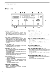
... cable can be used for HF band receiving, this terminal to a ground. !0 HF 500 Ω ANTENNA CONNECTOR (p. 8) When a 500 Ω long wire antenna is used to connect the IC-R8500 to cover the frequency range over 30 MHz. • Use a coaxial cable and type-N connector. 5... In this connector and the DC 13.8 V jack. • Be sure the jumper connector is not connected. *Not supplied with 9 V DC for the transceive function. Also connects to an Icom...
... cable can be used for HF band receiving, this terminal to a ground. !0 HF 500 Ω ANTENNA CONNECTOR (p. 8) When a 500 Ω long wire antenna is used to connect the IC-R8500 to cover the frequency range over 30 MHz. • Use a coaxial cable and type-N connector. 5... In this connector and the DC 13.8 V jack. • Be sure the jumper connector is not connected. *Not supplied with 9 V DC for the transceive function. Also connects to an Icom...
Instruction Manual
Page 11
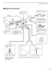
... in quick set mode (p. 31) 8 Ground connection (p. 9) VHF/UHF wide band antenna Long wire antenna HF antenna 30 MHz -2 GHz coverage The optional AH-7000 is available for 25 MHz to the [DC 13.8V] jack. 2 CONNECTIONS s Required connections IC-R8500 External speaker (p. 44) Connect either power source Supplied DC power cable Unplug the jumper...
... in quick set mode (p. 31) 8 Ground connection (p. 9) VHF/UHF wide band antenna Long wire antenna HF antenna 30 MHz -2 GHz coverage The optional AH-7000 is available for 25 MHz to the [DC 13.8V] jack. 2 CONNECTIONS s Required connections IC-R8500 External speaker (p. 44) Connect either power source Supplied DC power cable Unplug the jumper...
Instruction Manual
Page 12
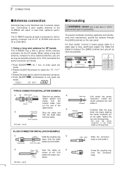
...and ground as short as solder shown at least 10 m, 33 ft) and select the active connector as the plug body. The IC-R8500 requires at least 2 antennas for full frequency coverage: one for 0.1 to 2000 MHz. For best results, connect a heavy gauge cable to exit quick set mode. 500... HF ANT s Grounding RWARNING: NEVER use one for 1 sec. D Using a long wire antenna for HF bands The IC-R8500 has a 500 Ω phono (RCA) antenna connector for grounding. cal conduit pipe for the HF bands. Strip the cable Coupling ring jacket and soft solder. 10 mm...
...and ground as short as solder shown at least 10 m, 33 ft) and select the active connector as the plug body. The IC-R8500 requires at least 2 antennas for full frequency coverage: one for 0.1 to 2000 MHz. For best results, connect a heavy gauge cable to exit quick set mode. 500... HF ANT s Grounding RWARNING: NEVER use one for 1 sec. D Using a long wire antenna for HF bands The IC-R8500 has a 500 Ω phono (RCA) antenna connector for grounding. cal conduit pipe for the HF bands. Strip the cable Coupling ring jacket and soft solder. 10 mm...

Instruction Manual
Page 34
... switches can be locked. Either the 50 Ω (SO-239 coaxial) or 500 Ω (phono RCA connector) can be activated. 50 500 The SO-239 antenna con- This announcement can be turned ON and OFF. ON Confirmation beeps ON (default). DIAL Only the main dial can be locked (default). The main... each time a switch is at a "low" level when the squelch opens via the [SPCH] switch only. 31 HF ANT This item sets the active HF antenna connector on the front panel. This function can be turned OFF for confirmation. LOCK This item sets the lock function to [2000] ×...
... switches can be locked. Either the 50 Ω (SO-239 coaxial) or 500 Ω (phono RCA connector) can be activated. 50 500 The SO-239 antenna con- This announcement can be turned ON and OFF. ON Confirmation beeps ON (default). DIAL Only the main dial can be locked (default). The main... each time a switch is at a "low" level when the squelch opens via the [SPCH] switch only. 31 HF ANT This item sets the active HF antenna connector on the front panel. This function can be turned OFF for confirmation. LOCK This item sets the lock function to [2000] ×...

Instruction Manual
Page 36
.../CTS) via the internal circuit board ('coffee beans'). 7 GND Grounded. 8 DCD NC; Grounded. Outer GND Grounded. *Output is selectable with -50 dBm input from an antenna connector in WFM mode) Grounded. can be connected to pin 8 (DCD) via the 20 DTR internal circuit board ('coffee beans'). 21-25 NC No connection...
.../CTS) via the internal circuit board ('coffee beans'). 7 GND Grounded. 8 DCD NC; Grounded. Outer GND Grounded. *Output is selectable with -50 dBm input from an antenna connector in WFM mode) Grounded. can be connected to pin 8 (DCD) via the 20 DTR internal circuit board ('coffee beans'). 21-25 NC No connection...

Instruction Manual
Page 43
...cable only. rect keypad entry. • The FM center indicator on your TV screen and sound is useful for tuning. • Pictures appear on the IC-R8500's function dis- play is emitted. ver- sion) 16.2 MHz (Europe version) • Audio carrier input frequency: 10.7 MHz • Audio intermediate ...8486; • Stereo separation: More than 30 dB (1 kHz) 40 s TV-R7100 TV RECEIVE ADAPTER D Connections 12 OPTIONAL INSTALLATIONS yellow white* red Antenna Red to right* White to left Yellow: no connection [IF OUT] red from [IF IN] [AGC] black from the ICR8500) • Current ...
...cable only. rect keypad entry. • The FM center indicator on your TV screen and sound is useful for tuning. • Pictures appear on the IC-R8500's function dis- play is emitted. ver- sion) 16.2 MHz (Europe version) • Audio carrier input frequency: 10.7 MHz • Audio intermediate ...8486; • Stereo separation: More than 30 dB (1 kHz) 40 s TV-R7100 TV RECEIVE ADAPTER D Connections 12 OPTIONAL INSTALLATIONS yellow white* red Antenna Red to right* White to left Yellow: no connection [IF OUT] red from [IF IN] [AGC] black from the ICR8500) • Current ...

Instruction Manual
Page 44
... 12 V DC is connected to the [DC IN] jack. • Reconnect the DC power cable securely. • Check for V/UHF and HF antenna. • Wrong antenna connector is selected in use of a problem or solve it OFF. • Push the correct mode switch. pgs. 13, 38 Sensitivity is low. ... is activated. ceiving frequency. • Check the antenna connection. • Select the proper antenna connector: SO-239 or phono (RCA). • Push [ATT 10 dB] or [ATT 20 dB] to locate the cause of this chart, contact your nearest Icom Dealer or Service Center. lected below 30 MHz.) Main...
... 12 V DC is connected to the [DC IN] jack. • Reconnect the DC power cable securely. • Check for V/UHF and HF antenna. • Wrong antenna connector is selected in use of a problem or solve it OFF. • Push the correct mode switch. pgs. 13, 38 Sensitivity is low. ... is activated. ceiving frequency. • Check the antenna connection. • Select the proper antenna connector: SO-239 or phono (RCA). • Push [ATT 10 dB] or [ATT 20 dB] to locate the cause of this chart, contact your nearest Icom Dealer or Service Center. lected below 30 MHz.) Main...

Instruction Manual
Page 46
... +50°C (+14°F to change without notice or obligation. 43 14 SPECIFICATIONS s General • Frequency coverage • Mode • Number of memory channels • Antenna connector • Usable temperature range • Frequency stability • Power supply requirement • Current drain (at 10% distortion with the optional AD-55/V) : Standby 1.8 A Max...
... +50°C (+14°F to change without notice or obligation. 43 14 SPECIFICATIONS s General • Frequency coverage • Mode • Number of memory channels • Antenna connector • Usable temperature range • Frequency stability • Power supply requirement • Current drain (at 10% distortion with the optional AD-55/V) : Standby 1.8 A Max...

Instruction Manual
Page 47
Does not comply with the IC-R8500; Input impedance: 8 Ω Max. CR-293 HIGH STABILITY CRYSTAL UNIT Provides improved frequency stability. • Frequency stability: ± 5 ppm (0°C-+60°C; 32°F-+140&#... can set and video recorder. MB-23 CARRYING HANDLE Designed for portable operation. input power: 5 W IC-MB12 MOBILE MOUNTING BRACKET Carrying handle, convenient for base station operation. AD-55/A/V AC ADAPTER For remote control of antenna: Discone Weight: 1 kg TV-R7100 TV RECEIVE ADAPTER SP-7 EXTERNAL SPEAKER Suitable for mobile operation. input...
Does not comply with the IC-R8500; Input impedance: 8 Ω Max. CR-293 HIGH STABILITY CRYSTAL UNIT Provides improved frequency stability. • Frequency stability: ± 5 ppm (0°C-+60°C; 32°F-+140&#... can set and video recorder. MB-23 CARRYING HANDLE Designed for portable operation. input power: 5 W IC-MB12 MOBILE MOUNTING BRACKET Carrying handle, convenient for base station operation. AD-55/A/V AC ADAPTER For remote control of antenna: Discone Weight: 1 kg TV-R7100 TV RECEIVE ADAPTER SP-7 EXTERNAL SPEAKER Suitable for mobile operation. input...

