Instruction Manual
Page 2
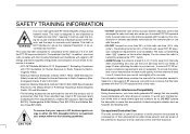
... sound quality, hold the antenna at the distance of 2.5 cm with the FCC RF exposure limits of your belt, etc., to Radio Frequency Electro- SAFETY TRAINING INFORMATION Your Icom radio generates RF electromagnetic energy during transmit mode. The information listed above provides the user with this product. This radio has been evaluated for "Occupational Use Only". Use of Potentially Hazardous Electromagnetic Fields- Belt Clip (MB- 86/103), Rechargeable...
... sound quality, hold the antenna at the distance of 2.5 cm with the FCC RF exposure limits of your belt, etc., to Radio Frequency Electro- SAFETY TRAINING INFORMATION Your Icom radio generates RF electromagnetic energy during transmit mode. The information listed above provides the user with this product. This radio has been evaluated for "Occupational Use Only". Use of Potentially Hazardous Electromagnetic Fields- Belt Clip (MB- 86/103), Rechargeable...
Instruction Manual
Page 3
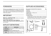
...- struction manual contains important operating instructions for purchasing this product should provide you for the IC-A24/A6. NOTE If disregarded, inconvenience only. No risk of the art technology and craftsmanship. With proper care this Icom product. IMPORTANT READ ALL INSTRUCTIONS carefully and completely before using the transceiver. FOREWORD SUPPLIED ACCESSORIES Thank you with years of trouble-free operation. The IC-A24/A6 VHF AIR BAND TRANSCEIVER is...
...- struction manual contains important operating instructions for purchasing this product should provide you for the IC-A24/A6. NOTE If disregarded, inconvenience only. No risk of the art technology and craftsmanship. With proper care this Icom product. IMPORTANT READ ALL INSTRUCTIONS carefully and completely before using the transceiver. FOREWORD SUPPLIED ACCESSORIES Thank you with years of trouble-free operation. The IC-A24/A6 VHF AIR BAND TRANSCEIVER is...
Instruction Manual
Page 4
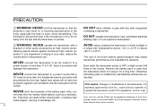
.../or other audio accessories at more than 5 A. be protected by Icom Inc., could void your ears, reduce the volume level or discontinue use of non-Icom battery packs/chargers may flow into nearby metal objects, such as a necklace, etc. FCC caution: Changes or modifications to a power source that the antenna is OFF, a slight current still damage the transceiver. flows...
.../or other audio accessories at more than 5 A. be protected by Icom Inc., could void your ears, reduce the volume level or discontinue use of non-Icom battery packs/chargers may flow into nearby metal objects, such as a necklace, etc. FCC caution: Changes or modifications to a power source that the antenna is OFF, a slight current still damage the transceiver. flows...

Instruction Manual
Page 5
... Setting a frequency 8 I Setting a squelch level 8 I Selecting a weather channel 8 I Receiving 9 I Transmitting 9 I ANL function 9 I Low battery indicator 10 I Recall function 10 I Setting weather alert function 11 I Accessing 121.5 MHz emergency frequency 11 I Lock function 11 I Side tone function 11 I Setting beep tone 11 I Backlighting 11 4 MEMORY OPERATION 12 - 15 I Memory channel selection 12 I Transferring memory contents 12 I Programming a memory channel 13 I Memory names 14 I Clearing the memory contents 14 5 SCAN OPERATION 16 - 17 I Scan types 16 I COM band scan...
... Setting a frequency 8 I Setting a squelch level 8 I Selecting a weather channel 8 I Receiving 9 I Transmitting 9 I ANL function 9 I Low battery indicator 10 I Recall function 10 I Setting weather alert function 11 I Accessing 121.5 MHz emergency frequency 11 I Lock function 11 I Side tone function 11 I Setting beep tone 11 I Backlighting 11 4 MEMORY OPERATION 12 - 15 I Memory channel selection 12 I Transferring memory contents 12 I Programming a memory channel 13 I Memory names 14 I Clearing the memory contents 14 5 SCAN OPERATION 16 - 17 I Scan types 16 I COM band scan...
Instruction Manual
Page 7
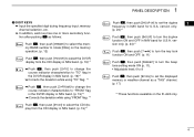
... MICROPHONE JACKS [MIC/SP] (p. 34) Connects an OPC-499 HEADSET ADAPTER and headset, if desired. !0 FUNCTION KEY Push to call the stored frequency in the recall mode. ➥ Push , then push [Ω]/[≈]to replace stored recall frequencies to transmit; In this time pushing again cancels the indication. i POWER SWITCH [PWR] (pgs. 9, 28) ➥ Push and hold to back or front. e VOLUME [VOL] (p. 9) Adjusts the audio level. w PTT SWITCH [PTT...
... MICROPHONE JACKS [MIC/SP] (p. 34) Connects an OPC-499 HEADSET ADAPTER and headset, if desired. !0 FUNCTION KEY Push to call the stored frequency in the recall mode. ➥ Push , then push [Ω]/[≈]to replace stored recall frequencies to transmit; In this time pushing again cancels the indication. i POWER SWITCH [PWR] (pgs. 9, 28) ➥ Push and hold to back or front. e VOLUME [VOL] (p. 9) Adjusts the audio level. w PTT SWITCH [PTT...

Instruction Manual
Page 8
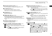
... while programming. ➥ Push to stop the scan function to turn the ANL function ON or OFF. ➥ Push , then push [ANL•SCAN] to start the scan function. !3 EMERGENCY KEY [121.5 MHz] (p. 11) Push for 11 24 V) (optional) !4 DC POWER JACK Connect the AC adapter or optional cable to charge the battery pack or to operate by external power supply. (see right illustration) !5 MEMORY MODE...
... while programming. ➥ Push to stop the scan function to turn the ANL function ON or OFF. ➥ Push , then push [ANL•SCAN] to start the scan function. !3 EMERGENCY KEY [121.5 MHz] (p. 11) Push for 11 24 V) (optional) !4 DC POWER JACK Connect the AC adapter or optional cable to charge the battery pack or to operate by external power supply. (see right illustration) !5 MEMORY MODE...
Instruction Manual
Page 9
... the deviation while using "FROM" flag. *1 Push , then push [4•CDI] to select the CDI display from the CDI display in NAV band. (p. 19)*1 PANEL DESCRIPTION 1 Push , then push [5•DUP-W] to set the displayed memory or weather channel as follows: Push , then push [0•BANK] to select the memory BANK number to rotate [DIAL] on the IC-A24 only. 4
... the deviation while using "FROM" flag. *1 Push , then push [4•CDI] to select the CDI display from the CDI display in NAV band. (p. 19)*1 PANEL DESCRIPTION 1 Push , then push [5•DUP-W] to set the displayed memory or weather channel as follows: Push , then push [0•BANK] to select the memory BANK number to rotate [DIAL] on the IC-A24 only. 4
Instruction Manual
Page 10
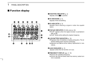
... recharging. ➥ Appears and flashes when battery replacement is in NAV mode. ➥"DUP" blinks while setting the duplex frequency. y LOCK INDICATOR (p. 11) Appears while the lock function is necessary. r DUPLEX INDICATOR (IC-A24 only) (p. 24) ➥"DUP" appears when the duplex function is pushed. e RX INDICATOR (p. 9) Appears when receiving a signal or when the squelch opens. w TX INDICATOR (p. 9) Appears while transmitting. 1 PANEL DESCRIPTION I Function display...
... recharging. ➥ Appears and flashes when battery replacement is in NAV mode. ➥"DUP" blinks while setting the duplex frequency. y LOCK INDICATOR (p. 11) Appears while the lock function is necessary. r DUPLEX INDICATOR (IC-A24 only) (p. 24) ➥"DUP" appears when the duplex function is pushed. e RX INDICATOR (p. 9) Appears when receiving a signal or when the squelch opens. w TX INDICATOR (p. 9) Appears while transmitting. 1 PANEL DESCRIPTION I Function display...

Instruction Manual
Page 13
w Push [SQL•WX-ALERT] or [CLR•DEL] to mute undesired 2 q Push [PWR] for 2 sec. I Setting a squelch level ï Using keypad The transceiver has a noise squelch circuit to exit the squelch set the desired frequency. version has VHF marine WX (weather) channel receiving capability for 2 sec. q Push , then push [ENT•WX] to select the 3 number or WX CH number appears on the function dis- w Rotate [DIAL...
w Push [SQL•WX-ALERT] or [CLR•DEL] to mute undesired 2 q Push [PWR] for 2 sec. I Setting a squelch level ï Using keypad The transceiver has a noise squelch circuit to exit the squelch set the desired frequency. version has VHF marine WX (weather) channel receiving capability for 2 sec. q Push , then push [ENT•WX] to select the 3 number or WX CH number appears on the function dis- w Rotate [DIAL...
Instruction Manual
Page 14
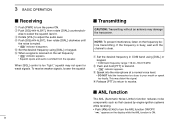
... the set frequency: • " " indicator appears. • Squelch opens and audio is received on the frequency before transmitting. q Set the desired frequency in COM band using [DIAL] or keypad. I ANL function The ANL (Automatic Noise Limiter) function reduces noise components such as that caused by engine ignition systems while receiving. • Push [ANL•SCAN] to adjust the audio level. 3 BASIC OPERATION I Receiving q Push [PWR] to receive. r Push [SQL•WX-ALERT...
... the set frequency: • " " indicator appears. • Squelch opens and audio is received on the frequency before transmitting. q Set the desired frequency in COM band using [DIAL] or keypad. I ANL function The ANL (Automatic Noise Limiter) function reduces noise components such as that caused by engine ignition systems while receiving. • Push [ANL•SCAN] to adjust the audio level. 3 BASIC OPERATION I Receiving q Push [PWR] to receive. r Push [SQL•WX-ALERT...
Instruction Manual
Page 16
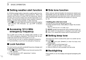
... the monitor level or discontinue use . 3 BASIC OPERATION I Setting weather alert function I Side tone function An NOAA broadcast station transmits a weather alert tone be acti- fore any time during standby, or while scanning. • Push , then push [SQL•WX-ALERT] to exit the beep tone set the beep level. When the weather alert function is turned ON, the transceiver detects the alert, and sounds a beep tone until the transceiver is Max. I Backlighting Push [LIGHT] to the headset for 2 sec. Connect...
... the monitor level or discontinue use . 3 BASIC OPERATION I Setting weather alert function I Side tone function An NOAA broadcast station transmits a weather alert tone be acti- fore any time during standby, or while scanning. • Push , then push [SQL•WX-ALERT] to exit the beep tone set the beep level. When the weather alert function is turned ON, the transceiver detects the alert, and sounds a beep tone until the transceiver is Max. I Backlighting Push [LIGHT] to the headset for 2 sec. Connect...

Instruction Manual
Page 18
...] to select the BANK number if desired. • Push [CLR•DEL], [ENT•WX] or , then push [0•BANK] to select a weather channel.* • Set the desired frequency or weather channel* using [DIAL] or keypad. t Push [ENT•WX] to program the information into the channel and return to select the frequency mode, if necessary. q Push [CLR•DEL] to the frequency mode. *Weather channel: U.S.A.
...] to select the BANK number if desired. • Push [CLR•DEL], [ENT•WX] or , then push [0•BANK] to select a weather channel.* • Set the desired frequency or weather channel* using [DIAL] or keypad. t Push [ENT•WX] to program the information into the channel and return to select the frequency mode, if necessary. q Push [CLR•DEL] to the frequency mode. *Weather channel: U.S.A.

Instruction Manual
Page 21
...-ALERT] to set the squelch level to select memory mode. Jump I COM band scan The U.S.A. version only. 16 5 SCAN OPERATION I Scan types I Memory scan MEMORY SCAN non-TAG channel Mch 2 Mch 4 Mch 6 Mch 1 Mch 19 Mch 10 Mch 7 non-TAG Mch 8 channel Repeatedly scans all "TAG" memory channels. r To stop the scan, push [CLR•DEL]. 5 Scan COM band. WEATHER CHANNEL SCAN Repeatedly scans all over frequencies the entire • When a signal is just muted...
...-ALERT] to set the squelch level to select memory mode. Jump I COM band scan The U.S.A. version only. 16 5 SCAN OPERATION I Scan types I Memory scan MEMORY SCAN non-TAG channel Mch 2 Mch 4 Mch 6 Mch 1 Mch 19 Mch 10 Mch 7 non-TAG Mch 8 channel Repeatedly scans all "TAG" memory channels. r To stop the scan, push [CLR•DEL]. 5 Scan COM band. WEATHER CHANNEL SCAN Repeatedly scans all over frequencies the entire • When a signal is just muted...
Instruction Manual
Page 25
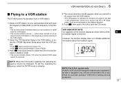
... a substitute for accurate (primary) VOR/CDI or landing service equipment. 20 The IC-A24 shows the deviation from the VOR station. lect the 'FROM' flag when flying away from the VOR station or the frequency is selected, the operating frequency cannot be received. NOTE: When the CDI mode is not set the operating frequency, select the DVOR mode in advance.
... a substitute for accurate (primary) VOR/CDI or landing service equipment. 20 The IC-A24 shows the deviation from the VOR station. lect the 'FROM' flag when flying away from the VOR station or the frequency is selected, the operating frequency cannot be received. NOTE: When the CDI mode is not set the operating frequency, select the DVOR mode in advance.
Instruction Manual
Page 29
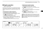
... the frequency mode. • "DUP" disappears on the function display. q Push [CLR•DEL] to transmit at the pre-programmed transmit frequency. EXAMPLE: Programming 123.65 MHz as the transmit frequency in advance. The duplex function requires frequency programming for the flight service station in the duplex function. 24 6 VOR NAVIGATION (IC-A24 ONLY) I Duplex operation (U.S.A. D Programming a duplex frequency r Release [PTT] to return to receive. 6 t Push , then push [6•DUP] to turn...
... the frequency mode. • "DUP" disappears on the function display. q Push [CLR•DEL] to transmit at the pre-programmed transmit frequency. EXAMPLE: Programming 123.65 MHz as the transmit frequency in advance. The duplex function requires frequency programming for the flight service station in the duplex function. 24 6 VOR NAVIGATION (IC-A24 ONLY) I Duplex operation (U.S.A. D Programming a duplex frequency r Release [PTT] to return to receive. 6 t Push , then push [6•DUP] to turn...

Instruction Manual
Page 30
... it may be sure to wipe it dry immediately (particularly the battery terminals BEFORE attaching it to +104°F) - Then, fully charge the battery pack again. CAUTION: To avoid damage to the transceiver, turn the power OFF while charging. • Recommended temperature range for optimum life and operation. CAUTION! The charger is not waterproof and water can easily get into the...
... it may be sure to wipe it dry immediately (particularly the battery terminals BEFORE attaching it to +104°F) - Then, fully charge the battery pack again. CAUTION: To avoid damage to the transceiver, turn the power OFF while charging. • Recommended temperature range for optimum life and operation. CAUTION! The charger is not waterproof and water can easily get into the...
Instruction Manual
Page 33
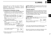
...;nished, turn power OFF, then ON again to another when the data contains the NAV band data. Consult the CS-A24 ceiver. e Push [MR•MW] on the slave transceiver during cloning. 8 CLONING Cloning allows you to quickly and easily transfer the NOTE: DO NOT transfer the data from IC-A24 to IC-A6, programmed data from one transceiver to exit cloning mode. 28 SOFTWARE and...
...;nished, turn power OFF, then ON again to another when the data contains the NAV band data. Consult the CS-A24 ceiver. e Push [MR•MW] on the slave transceiver during cloning. 8 CLONING Cloning allows you to quickly and easily transfer the NOTE: DO NOT transfer the data from IC-A24 to IC-A6, programmed data from one transceiver to exit cloning mode. 28 SOFTWARE and...

Instruction Manual
Page 34
... beep tone level 29 channels. 9 TROUBLESHOOTING If your transceiver seems to be selected. • Lock function is too deep. p. 17 No beep sounds. • Beep tones turned OFF. • Push , then push [8•BEEP] to a service center. the speaker. • Volume level is exhausted. • Bad connection for the battery pack. • Recharge the battery pack. PROBLEM POSSIBLE CAUSE SOLUTION REF. No power comes on. • The battery is too low. • Set squelch...
... beep tone level 29 channels. 9 TROUBLESHOOTING If your transceiver seems to be selected. • Lock function is too deep. p. 17 No beep sounds. • Beep tones turned OFF. • Push , then push [8•BEEP] to a service center. the speaker. • Volume level is exhausted. • Bad connection for the battery pack. • Recharge the battery pack. PROBLEM POSSIBLE CAUSE SOLUTION REF. No power comes on. • The battery is too low. • Set squelch...
Instruction Manual
Page 35
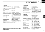
...fied battery packs/case or • Output power • Modulation • Modulation limiting • Audio harmonic distortion • Hum and noise ratio • Spurious emissions • Microphone connector : 5 W (PEP) typical 1.5 W (CW) typical : Low level modulation : 70 to change without notice or obligation. • External SP connector : 3-conductor 3.5 (d) mm (1/8˝)/8 Ω 30 10 SPECIFICATIONS D General D Transmitter • Frequency coverage (MHz): TX...
...fied battery packs/case or • Output power • Modulation • Modulation limiting • Audio harmonic distortion • Hum and noise ratio • Spurious emissions • Microphone connector : 5 W (PEP) typical 1.5 W (CW) typical : Low level modulation : 70 to change without notice or obligation. • External SP connector : 3-conductor 3.5 (d) mm (1/8˝)/8 Ω 30 10 SPECIFICATIONS D General D Transmitter • Frequency coverage (MHz): TX...

Instruction Manual
Page 36
... AC adapter is supplied with the transceiver. •BC-119N DESKTOP CHARGER + AD-101 CHARGER ADAPTER + BC-145 AC ADAPTER For rapid charging of BP-209N (Ni-Cd) and BP-210N (Ni-MH). via the adapter, the transceiver outputs your authorized dealer for swivel type. D DC CABLES • CP-20 CIGARETTE LIGHTER CABLE ➥Charges the battery pack through a cigarette lighter socket*. ➥Operates IC-A24/A6...
... AC adapter is supplied with the transceiver. •BC-119N DESKTOP CHARGER + AD-101 CHARGER ADAPTER + BC-145 AC ADAPTER For rapid charging of BP-209N (Ni-Cd) and BP-210N (Ni-MH). via the adapter, the transceiver outputs your authorized dealer for swivel type. D DC CABLES • CP-20 CIGARETTE LIGHTER CABLE ➥Charges the battery pack through a cigarette lighter socket*. ➥Operates IC-A24/A6...


