Hardware Maintenance Manual
Page 5
... 40 Strategy for replacing FRUs for CTO, CMV, and GAV 41 Product definition 41 FRU identification for CTO, CMV, and GAV products 41 General checkout 43 What to do first 44 Checkout guide 45 Diagnostics using PC-Doctor for DOS . . . . 45 Lenovo ThinkVantage Toolbox (Lenovo System Toolbox 48 ... Bluetooth daughter card (BDC-2) . . . . . 103 1150 Media Card Reader slot board and Media Card Reader cable assembly 104 1160 Keyboard 106 1170 Keyboard bezel 109 1180 LCD unit 111 1190 Top shielding assembly 116 1200 System board assembly 118 1210 USB connector board and USB cable assembly...
... 40 Strategy for replacing FRUs for CTO, CMV, and GAV 41 Product definition 41 FRU identification for CTO, CMV, and GAV products 41 General checkout 43 What to do first 44 Checkout guide 45 Diagnostics using PC-Doctor for DOS . . . . 45 Lenovo ThinkVantage Toolbox (Lenovo System Toolbox 48 ... Bluetooth daughter card (BDC-2) . . . . . 103 1150 Media Card Reader slot board and Media Card Reader cable assembly 104 1160 Keyboard 106 1170 Keyboard bezel 109 1180 LCD unit 111 1190 Top shielding assembly 116 1200 System board assembly 118 1210 USB connector board and USB cable assembly...
Hardware Maintenance Manual
Page 70
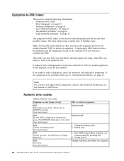
...of symptoms. If the symptom is not described there, go to EEPROM is displayed for that device. Charge the battery pack. 2. Do not replace a nondefective FRU. A numeric error is failed. (two short beeps) System board. 0189 System board. Numeric error codes Table 2. Numeric error... beeps) 1. Note: Do the FRU replacement or other actions in the sequence shown in the column headed "FRU or action, in boldface type. System board. 0210 Stuck Key (two short beeps) Change keyboard, and restart the computer. 62 ThinkPad SL410, L410, SL510, and L510 Hardware Maintenance Manual
...of symptoms. If the symptom is not described there, go to EEPROM is displayed for that device. Charge the battery pack. 2. Do not replace a nondefective FRU. A numeric error is failed. (two short beeps) System board. 0189 System board. Numeric error codes Table 2. Numeric error... beeps) 1. Note: Do the FRU replacement or other actions in the sequence shown in the column headed "FRU or action, in boldface type. System board. 0210 Stuck Key (two short beeps) Change keyboard, and restart the computer. 62 ThinkPad SL410, L410, SL510, and L510 Hardware Maintenance Manual
Hardware Maintenance Manual
Page 71
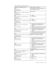
...Utility to reset the time and date. 0280 Previous boot incomplete- Then restart the computer. 0260 System timer error. (two short beeps) 1. Replace the backup battery and run BIOS Setup Utility to reset the time and date. 3. DIMM. 3. CPU. 2. Related service information 63 Charge ...keyboard and the auxiliary input device. 0230 Shadow RAM error-Shadow RAM fails at offset nnnn. (two short beeps) System board. 0231 System RAM error-System RAM fails at offset nnnn. (two short beeps) 1. Charge the backup battery for more than 8 hours by connecting the ac adapter. 2. Replace...
...Utility to reset the time and date. 0280 Previous boot incomplete- Then restart the computer. 0260 System timer error. (two short beeps) 1. Replace the backup battery and run BIOS Setup Utility to reset the time and date. 3. DIMM. 3. CPU. 2. Related service information 63 Charge ...keyboard and the auxiliary input device. 0230 Shadow RAM error-Shadow RAM fails at offset nnnn. (two short beeps) System board. 0231 System RAM error-System RAM fails at offset nnnn. (two short beeps) 1. Charge the backup battery for more than 8 hours by connecting the ac adapter. 2. Replace...

Hardware Maintenance Manual
Page 107
Installation of the keyboard bezel as shown in this figure. Attach the palm rest so that the two small projections of the palm rest ( a ) firmly fit into place. 4. Push the front side of the palm rest until it clicks into the guide holes of palm rest assembly with cables When installing: 1. a a 3. Attach the cables to secure the palm rest. Close the LCD cover and turn the computer over. Then fasten the screws to the system board firmly. 2. Table 20. Removing and replacing a FRU 99
Installation of the keyboard bezel as shown in this figure. Attach the palm rest so that the two small projections of the palm rest ( a ) firmly fit into place. 4. Push the front side of the palm rest until it clicks into the guide holes of palm rest assembly with cables When installing: 1. a a 3. Attach the cables to secure the palm rest. Close the LCD cover and turn the computer over. Then fasten the screws to the system board firmly. 2. Table 20. Removing and replacing a FRU 99

Hardware Maintenance Manual
Page 115
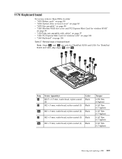
Removal steps of keyboard (continued) 6 7 2 4 2 3 5 Step 6 Screw (quantity) M2 × 3 mm, wafer-head, nylon-coated (1) Color Black 7 M2 × 2 mm, wafer-head, nylon-coated (1) Silver Torque 0.167 Nm (1.7 kgfcm) 0.167 Nm (1.7 kgfcm) 8 Removing and replacing a FRU 107 Table 25.
Removal steps of keyboard (continued) 6 7 2 4 2 3 5 Step 6 Screw (quantity) M2 × 3 mm, wafer-head, nylon-coated (1) Color Black 7 M2 × 2 mm, wafer-head, nylon-coated (1) Silver Torque 0.167 Nm (1.7 kgfcm) 0.167 Nm (1.7 kgfcm) 8 Removing and replacing a FRU 107 Table 25.
Hardware Maintenance Manual
Page 117
1170 Keyboard bezel For access, remove these FRUs in order: v "1010 Battery pack" on page 80 v "1030 Optical drive or travel cover... Note: Steps 2a and 3a are only for wireless LAN" on page 100 v "1160 Keyboard" on page 97 v "1120 PCI Express Mini Card for ThinkPad SL510 and L510. For ThinkPad SL410 and L410, skip steps 2a and 3a . 3 3 1 2 2 2a 2a 2 1 3a 3 Step 1 2 Screw (quantity) M2.5 × 6.5 mm, wafer-head, ...nylon-coated (1) Black Torque 0.392 Nm (4 kgfcm) 0.167 Nm (1.7 kgfcm) 0.167 Nm (1.7 kgfcm) 0.167 Nm (1.7 kgfcm) 0.167 Nm (1.7 kgfcm) Removing and replacing a FRU 109
1170 Keyboard bezel For access, remove these FRUs in order: v "1010 Battery pack" on page 80 v "1030 Optical drive or travel cover... Note: Steps 2a and 3a are only for wireless LAN" on page 100 v "1160 Keyboard" on page 97 v "1120 PCI Express Mini Card for ThinkPad SL510 and L510. For ThinkPad SL410 and L410, skip steps 2a and 3a . 3 3 1 2 2 2a 2a 2 1 3a 3 Step 1 2 Screw (quantity) M2.5 × 6.5 mm, wafer-head, ...nylon-coated (1) Black Torque 0.392 Nm (4 kgfcm) 0.167 Nm (1.7 kgfcm) 0.167 Nm (1.7 kgfcm) 0.167 Nm (1.7 kgfcm) 0.167 Nm (1.7 kgfcm) Removing and replacing a FRU 109

Hardware Maintenance Manual
Page 119
1180 LCD unit For access, remove these FRUs in order: v "1010 Battery pack" on page 80 v "1030 Optical drive or travel cover" on page 83 v "1100 Wireless WAN slot cover and PCI Express Mini Card for wireless WAN" on page 95 v "1110 Palm rest assembly with cables" on page 97 v "1120 PCI Express Mini Card for wireless LAN" on page 100 v "1160 Keyboard" on page 106 v "1170 Keyboard bezel" on page 109 Table 28. Removal steps of LCD unit 1 1 Step 1 Screw (quantity) M2.5 × 6.5 mm, wafter-head, nylon-coated (2) Color Black Torque 0.392 Nm (4 kgfcm) Removing and replacing a FRU 111
1180 LCD unit For access, remove these FRUs in order: v "1010 Battery pack" on page 80 v "1030 Optical drive or travel cover" on page 83 v "1100 Wireless WAN slot cover and PCI Express Mini Card for wireless WAN" on page 95 v "1110 Palm rest assembly with cables" on page 97 v "1120 PCI Express Mini Card for wireless LAN" on page 100 v "1160 Keyboard" on page 106 v "1170 Keyboard bezel" on page 109 Table 28. Removal steps of LCD unit 1 1 Step 1 Screw (quantity) M2.5 × 6.5 mm, wafter-head, nylon-coated (2) Color Black Torque 0.392 Nm (4 kgfcm) Removing and replacing a FRU 111

Hardware Maintenance Manual
Page 127
... Bluetooth daughter card (BDC-2)" on page 103 v "1150 Media Card Reader slot board and Media Card Reader cable assembly" on page 104 v "1160 Keyboard" on page 106 v "1170 Keyboard bezel" on page 109 v "1180 LCD unit" on page 111 v "1190 Top shielding assembly" on the top side of the system board are... Card for wireless WAN" on page 95 v "1110 Palm rest assembly with cables" on page 97 v "1120 PCI Express Mini Card for discrete models) For ThinkPad SL410 and L410 integrated models: a b c Removing and replacing a FRU 119 Location of rough handling.
... Bluetooth daughter card (BDC-2)" on page 103 v "1150 Media Card Reader slot board and Media Card Reader cable assembly" on page 104 v "1160 Keyboard" on page 106 v "1170 Keyboard bezel" on page 109 v "1180 LCD unit" on page 111 v "1190 Top shielding assembly" on the top side of the system board are... Card for wireless WAN" on page 95 v "1110 Palm rest assembly with cables" on page 97 v "1120 PCI Express Mini Card for discrete models) For ThinkPad SL410 and L410 integrated models: a b c Removing and replacing a FRU 119 Location of rough handling.

Hardware Maintenance Manual
Page 131
Step 2 Screw (quantity) M2 × 3 mm, wafer-head, nylon-coated (1) Color Black Torque 0.167 Nm (1.7 kgfcm) Removing and replacing a FRU 123 1210 USB connector board and USB cable assembly For access, remove these FRUs in order: v "1010 Battery pack" on page 80 v "1040 Thermal ... Card for wireless LAN" on page 100 v "1150 Media Card Reader slot board and Media Card Reader cable assembly" on page 104 v "1160 Keyboard" on page 106 v "1170 Keyboard bezel" on page 109 v "1180 LCD unit" on page 111 v "1190 Top shielding assembly" on page 116 Table 32. Removal steps of USB...
Step 2 Screw (quantity) M2 × 3 mm, wafer-head, nylon-coated (1) Color Black Torque 0.167 Nm (1.7 kgfcm) Removing and replacing a FRU 123 1210 USB connector board and USB cable assembly For access, remove these FRUs in order: v "1010 Battery pack" on page 80 v "1040 Thermal ... Card for wireless LAN" on page 100 v "1150 Media Card Reader slot board and Media Card Reader cable assembly" on page 104 v "1160 Keyboard" on page 106 v "1170 Keyboard bezel" on page 109 v "1180 LCD unit" on page 111 v "1190 Top shielding assembly" on page 116 Table 32. Removal steps of USB...
Hardware Maintenance Manual
Page 133
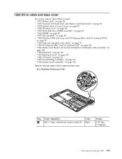
... page 106 v "1170 Keyboard bezel" on page 109 v "1180 LCD unit" on page 111 v "1190 Top shielding assembly" on page 116 v "1200 System board assembly" on page 118 Table 33. 1220 DC-in cable and base cover For access, remove these FRUs in cable and base cover For ThinkPad SL510 and L510: 1 3 2 ...1 Step 1 Screw (quantity) M2 × 3 mm, wafer-head, nylon-coated (2) Color Black Torque 0.167 Nm (1.7 kgfcm) Removing and replacing a FRU 125
... page 106 v "1170 Keyboard bezel" on page 109 v "1180 LCD unit" on page 111 v "1190 Top shielding assembly" on page 116 v "1200 System board assembly" on page 118 Table 33. 1220 DC-in cable and base cover For access, remove these FRUs in cable and base cover For ThinkPad SL510 and L510: 1 3 2 ...1 Step 1 Screw (quantity) M2 × 3 mm, wafer-head, nylon-coated (2) Color Black Torque 0.167 Nm (1.7 kgfcm) Removing and replacing a FRU 125

Hardware Maintenance Manual
Page 139
... page 95 v "1110 Palm rest assembly with cables" on page 97 v "1120 PCI Express Mini Card for wireless LAN" on page 100 v "1160 Keyboard" on page 106 v "1170 Keyboard bezel" on page 109 v "1180 LCD unit" on page 111 v "2010 LCD front bezel" on page 130 Table 35. Removal steps of speaker...
... page 95 v "1110 Palm rest assembly with cables" on page 97 v "1120 PCI Express Mini Card for wireless LAN" on page 100 v "1160 Keyboard" on page 106 v "1170 Keyboard bezel" on page 109 v "1180 LCD unit" on page 111 v "2010 LCD front bezel" on page 130 Table 35. Removal steps of speaker...
Hardware Maintenance Manual
Page 141
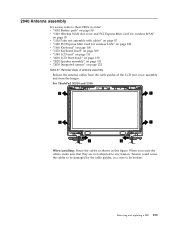
For ThinkPad SL510 and L510: 1 1 1 1 1 1 When installing: Route the cables as shown in order: v "1010 Battery pack" on ... rest assembly with cables" on page 97 v "1120 PCI Express Mini Card for wireless LAN" on page 100 v "1160 Keyboard" on page 106 v "1170 Keyboard bezel" on page 109 v "1180 LCD unit" on page 111 v "2010 LCD front bezel" on page 130 v "...Tension could cause the cables to be damaged by the cable guides, or a wire to any tension. Removing and replacing a FRU 133 Removal steps of antenna assembly Release the antenna cables from the cable guides of the LCD rear cover ...
For ThinkPad SL510 and L510: 1 1 1 1 1 1 When installing: Route the cables as shown in order: v "1010 Battery pack" on ... rest assembly with cables" on page 97 v "1120 PCI Express Mini Card for wireless LAN" on page 100 v "1160 Keyboard" on page 106 v "1170 Keyboard bezel" on page 109 v "1180 LCD unit" on page 111 v "2010 LCD front bezel" on page 130 v "...Tension could cause the cables to be damaged by the cable guides, or a wire to any tension. Removing and replacing a FRU 133 Removal steps of antenna assembly Release the antenna cables from the cable guides of the LCD rear cover ...
Hardware Maintenance Manual
Page 143
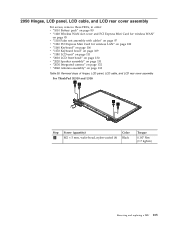
... page 95 v "1110 Palm rest assembly with cables" on page 97 v "1120 PCI Express Mini Card for wireless LAN" on page 100 v "1160 Keyboard" on page 106 v "1170 Keyboard bezel" on page 109 v "1180 LCD unit" on page 111 v "2010 LCD front bezel" on page 130 v "2020 Speaker assembly" on page 131..." on page 132 v "2040 Antenna assembly" on page 133 Table 38. Removal steps of hinges, LCD panel, LCD cable, and LCD rear cover assembly For ThinkPad SL510 and L510: 1 1 1 1 Step 1 Screw (quantity) M2 × 5 mm, wafer-head, nylon-coated (4) Color Black Torque 0.167 Nm (1.7 kgfcm) Removing and...
... page 95 v "1110 Palm rest assembly with cables" on page 97 v "1120 PCI Express Mini Card for wireless LAN" on page 100 v "1160 Keyboard" on page 106 v "1170 Keyboard bezel" on page 109 v "1180 LCD unit" on page 111 v "2010 LCD front bezel" on page 130 v "2020 Speaker assembly" on page 131..." on page 132 v "2040 Antenna assembly" on page 133 Table 38. Removal steps of hinges, LCD panel, LCD cable, and LCD rear cover assembly For ThinkPad SL510 and L510: 1 1 1 1 Step 1 Screw (quantity) M2 × 5 mm, wafer-head, nylon-coated (4) Color Black Torque 0.167 Nm (1.7 kgfcm) Removing and...
Hardware Maintenance Manual
Page 149
...touchpad. A single asterisk (*) means that the part is specified. ThinkPad computers contain the following lists of the service parts. v FRU..."Common service tools" on product design may include a memory, a wireless card, a keyboard, and a palm rest with OP are available as xxU (where U is not a... FRU with specific models listed and described as options. © Copyright Lenovo 2009 141 An N in the CRU ID column. Once the access ...should be used for all models ending in U. v A CRU (customer replaceable unit) is identified by a single asterisk (*) or two asterisks (**) in ...
...touchpad. A single asterisk (*) means that the part is specified. ThinkPad computers contain the following lists of the service parts. v FRU..."Common service tools" on product design may include a memory, a wireless card, a keyboard, and a palm rest with OP are available as xxU (where U is not a... FRU with specific models listed and described as options. © Copyright Lenovo 2009 141 An N in the CRU ID column. Once the access ...should be used for all models ending in U. v A CRU (customer replaceable unit) is identified by a single asterisk (*) or two asterisks (**) in ...

