User Guide
Page 5
...Identifying parts on the rear of your computer 7 Locating the connectors on the system board . . . . . 11 Installing memory 12 Installing adapters 14 Installing internal drives 16 Drive specifications 16 Installing a drive 17 Installing security features 20 Padlock loop 21 ...35 MNP/V.42/V.42bis/V.44 commands 36 Fax Class 1 commands 37 Fax Class 2 commands 37 Voice commands 38 Appendix D. Portions © IBM Corp. 2004,2005. iii Installing options 1 Features 1 Specifications 4 Available options 5 Tools required 5 Handling static-sensitive devices 5 Installing ...
...Identifying parts on the rear of your computer 7 Locating the connectors on the system board . . . . . 11 Installing memory 12 Installing adapters 14 Installing internal drives 16 Drive specifications 16 Installing a drive 17 Installing security features 20 Padlock loop 21 ...35 MNP/V.42/V.42bis/V.44 commands 36 Fax Class 1 commands 37 Fax Class 2 commands 37 Voice commands 38 Appendix D. Portions © IBM Corp. 2004,2005. iii Installing options 1 Features 1 Specifications 4 Available options 5 Tools required 5 Handling static-sensitive devices 5 Installing ...
User Guide
Page 17
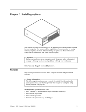
Note: Use only the parts provided by adding memory, adapters, or drives. See Chapter 2, "Using the Setup Utility ... will help you install or remove any option, read "Important safety information" on page 25. Installing options ThinkCentre Features This chapter provides an introduction to the features and options that come with HyperThreading Technology v Intel Pentium ... option. Microprocessor (varies by model type) © Lenovo 2005. Portions © IBM Corp. 2004,2005. 1 Important Before you work safely. When installing an option, use the Setup Utility. Chapter 1.
Note: Use only the parts provided by adding memory, adapters, or drives. See Chapter 2, "Using the Setup Utility ... will help you install or remove any option, read "Important safety information" on page 25. Installing options ThinkCentre Features This chapter provides an introduction to the features and options that come with HyperThreading Technology v Intel Pentium ... option. Microprocessor (varies by model type) © Lenovo 2005. Portions © IBM Corp. 2004,2005. 1 Important Before you work safely. When installing an option, use the Setup Utility. Chapter 1.
User Guide
Page 18
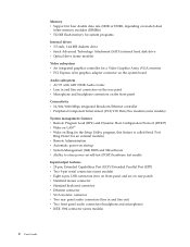
... four double data rate (DDR or DDR2, depending on model) dual inline memory modules (DIMMs) v 512 KB flash memory for system programs Internal drives v 3.5-inch, 1.44 MB diskette drive v Serial Advanced Technology Attachment (SATA) internal hard disk drive v Optical drive (some models) Video subsystem v An integrated graphics controller for a Video Graphics Array (...
... four double data rate (DDR or DDR2, depending on model) dual inline memory modules (DIMMs) v 512 KB flash memory for system programs Internal drives v 3.5-inch, 1.44 MB diskette drive v Serial Advanced Technology Attachment (SATA) internal hard disk drive v Optical drive (some models) Video subsystem v An integrated graphics controller for a Video Graphics Array (...

User Guide
Page 21
... 1-800-426-2968. Hard disk drive - Movement can cause static electricity to build up around you might be needed for the sound system - System memory, called dual inline memory modules (DIMMs) - PCI Express (x16) graphics adapter - Internal drives, such as printers, joysticks, and scanners - Diskette drives and other computer components, take these...
... 1-800-426-2968. Hard disk drive - Movement can cause static electricity to build up around you might be needed for the sound system - System memory, called dual inline memory modules (DIMMs) - PCI Express (x16) graphics adapter - Internal drives, such as printers, joysticks, and scanners - Diskette drives and other computer components, take these...

User Guide
Page 22
... option. 6 User Guide When adding an external option, use the information in addition to a metal expansion-slot cover or other metal surface. Handle adapters and memory modules by the edges. For some external options, you must install additional software in this is not possible, place the static-protective package that come...
... option. 6 User Guide When adding an external option, use the information in addition to a metal expansion-slot cover or other metal surface. Handle adapters and memory modules by the edges. For some external options, you must install additional software in this is not possible, place the static-protective package that come...

User Guide
Page 27
... computer functions and supports a variety of devices that are factory-installed or that you locate the various components in your computer. * XXXXXXXXX* * XXXXXXXXX* 1 Power supply 2 Memory modules 3 PCI Express (x1) adapter connector 4 PCI adapter connector 5 PCI Express (x16) graphics adapter connector 6 Battery 7 Microprocessor and heat sink Identifying parts on the system...
... computer functions and supports a variety of devices that are factory-installed or that you locate the various components in your computer. * XXXXXXXXX* * XXXXXXXXX* 1 Power supply 2 Memory modules 3 PCI Express (x1) adapter connector 4 PCI adapter connector 5 PCI Express (x16) graphics adapter connector 6 Battery 7 Microprocessor and heat sink Identifying parts on the system...

User Guide
Page 28
... system board that provide up to a maximum of 4.0 GB of memory required depends on the system board. 1 12v power connector 2 Diskette drive connector 3 Speaker connector 4 Memory connector 4 5 Memory connector 3 6 Memory connector 2 7 Memory connector 1 8 Clear CMOS/Recovery jumper 9 Front panel connector 10 ...1 21 Battery 22 Microprocessor 23 Microprocessor fan connector 24 Microprocessor heat sink Installing memory Your computer has four connectors for installing dual inline memory modules (DIMMs) that is divided into two channels (channel A and B). Note: Addressable...
... system board that provide up to a maximum of 4.0 GB of memory required depends on the system board. 1 12v power connector 2 Diskette drive connector 3 Speaker connector 4 Memory connector 4 5 Memory connector 3 6 Memory connector 2 7 Memory connector 1 8 Clear CMOS/Recovery jumper 9 Front panel connector 10 ...1 21 Battery 22 Microprocessor 23 Microprocessor fan connector 24 Microprocessor heat sink Installing memory Your computer has four connectors for installing dual inline memory modules (DIMMs) that is divided into two channels (channel A and B). Note: Addressable...
User Guide
Page 29
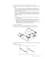
...to the edge of the system board are 184-pin, 2.5 V and can be less than 3.0 GB of 128 MB, 256 MB, 512 MB, and 1 GB sizes. Open the retaining clips. Locate the memory connectors. This discrepancy is due to the edge of the system board are 240-pin, 1.8 V and can be ... operating system might be used in any combination of 256 MB, 512 MB, and 1 GB sizes. Notes: a. See "Identifying parts on the system board" on page 10. 2. v If the two memory connectors closest to the system board. * XXXXXXXXX* * XXXXXXXXX* 3. System memory as reported in text near the logo on the system ...
...to the edge of the system board are 184-pin, 2.5 V and can be less than 3.0 GB of 128 MB, 256 MB, 512 MB, and 1 GB sizes. Open the retaining clips. Locate the memory connectors. This discrepancy is due to the edge of the system board are 240-pin, 1.8 V and can be ... operating system might be used in any combination of 256 MB, 512 MB, and 1 GB sizes. Notes: a. See "Identifying parts on the system board" on page 10. 2. v If the two memory connectors closest to the system board. * XXXXXXXXX* * XXXXXXXXX* 3. System memory as reported in text near the logo on the system ...

User Guide
Page 30
... go to 340 mm (13.4 inches) long in PCI adapter connector 1 and PCI adapter connector 2. Push the memory module straight down into the memory connector until the retaining clips close. See "Removing the cover" on the system board. Installing adapters This section provides..., and one PCI Express (x16) graphics adapter connector. Your computer has two expansion connectors for installing and removing adapters. Position the memory module over the memory connector. To install an adapter: 1. What to the system board. * XXXXXXXXX* * XXXXXXXXX* 14 User Guide 5. You can install...
... go to 340 mm (13.4 inches) long in PCI adapter connector 1 and PCI adapter connector 2. Push the memory module straight down into the memory connector until the retaining clips close. See "Removing the cover" on the system board. Installing adapters This section provides..., and one PCI Express (x16) graphics adapter connector. Your computer has two expansion connectors for installing and removing adapters. Position the memory module over the memory connector. To install an adapter: 1. What to the system board. * XXXXXXXXX* * XXXXXXXXX* 14 User Guide 5. You can install...

User Guide
Page 37
... information (including passwords) are lost. Padlock loop Your computer is equipped with a padlock loop that locks the cover to your computer, you can use of memory that the padlock loop does not interfere with another option, go to "Replacing the cover and connecting the cables" on page 25.
... information (including passwords) are lost. Padlock loop Your computer is equipped with a padlock loop that locks the cover to your computer, you can use of memory that the padlock loop does not interfere with another option, go to "Replacing the cover and connecting the cables" on page 25.

User Guide
Page 41
...which operating system you type your computer, you should read and understand the following : 1. The Setup Utility might override any passwords, read -only memory (EEPROM) of each screen. The keys used to use the keyboard. Password considerations If you are available: v User Password v Administrator Password v... multiple beeps, release the F1 key. However, if you can set any similar settings in your computer and data. Portions © IBM Corp. 2004,2005. 25 Using the Setup Utility program The Setup Utility program is not displayed until you are using a USB keyboard ...
...which operating system you type your computer, you should read and understand the following : 1. The Setup Utility might override any passwords, read -only memory (EEPROM) of each screen. The keys used to use the keyboard. Password considerations If you are available: v User Password v Administrator Password v... multiple beeps, release the F1 key. However, if you can set any similar settings in your computer and data. Portions © IBM Corp. 2004,2005. 25 Using the Setup Utility program The Setup Utility program is not displayed until you are using a USB keyboard ...
User Guide
Page 45
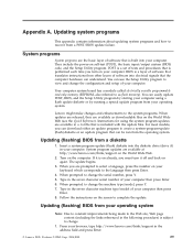
... computer. Updating (flashing) BIOS from a POST/BIOS update failure. Follow the instructions on the World Wide Web. 2. Portions © IBM Corp. 2004,2005. 29 You can be run from your browser, type http://www.lenovo.com/think /support on the screen to change... When prompted to the language then press Enter. 4. Appendix A. Your computer system board has a module called electrically erasable programmable read-only memory (EEPROM, also referred to view and change the machine type/model, press Y. 7. Instructions for using a flash update diskette or by starting...
... computer. Updating (flashing) BIOS from a POST/BIOS update failure. Follow the instructions on the World Wide Web. 2. Portions © IBM Corp. 2004,2005. 29 You can be run from your browser, type http://www.lenovo.com/think /support on the screen to change... When prompted to the language then press Enter. 4. Appendix A. Your computer system board has a module called electrically erasable programmable read-only memory (EEPROM, also referred to view and change the machine type/model, press Y. 7. Instructions for using a flash update diskette or by starting...

User Guide
Page 49
... one , it is not supported for five seconds of silence flash return to your modem. All commands can be typed in the modem non-volatile memory. Example: ATH [ENTER] Basic AT commands In the following section lists commands for manually programming your modem from Data Mode to the modem must begin... you omit a parameter from a command that requires one of 0. Command) Force modem on-hook (hang up) © Lenovo 2005. Repeat last command executed. Portions © IBM Corp. 2004,2005. 33
... one , it is not supported for five seconds of silence flash return to your modem. All commands can be typed in the modem non-volatile memory. Example: ATH [ENTER] Basic AT commands In the following section lists commands for manually programming your modem from Data Mode to the modem must begin... you omit a parameter from a command that requires one of 0. Command) Force modem on-hook (hang up) © Lenovo 2005. Repeat last command executed. Portions © IBM Corp. 2004,2005. 33

User Guide
Page 50
... Guide Function Force modem off-hook (make busy) Note: H1 command is not supported for Italy Display product-identification code Factory ROM checksum test Internal memory test Firmware ID Reserved ID Low speaker volume Low speaker volume Medium speaker volume High speaker volume Internal speaker off Internal speaker on until carrier...
... Guide Function Force modem off-hook (make busy) Note: H1 command is not supported for Italy Display product-identification code Factory ROM checksum test Internal memory test Firmware ID Reserved ID Low speaker volume Low speaker volume Medium speaker volume High speaker volume Internal speaker off Internal speaker on until carrier...
User Guide
Page 59
Portions © IBM Corp. 2004,2005. Index A adapters connectors 14 installing 14 peripheral component interconnect (PCI) 5 audio line in connector 9 audio line out connector 9 audio, subsystem 2 B battery ... Ethernet connector 9 I information resources xiii input/output (I/O) features 2 installing options adapters 14 internal drives 17 memory modules 12, 13 © Lenovo 2005. installing options (continued) security features 20 K keyboard connector 9 L locating components 11 M memory dual inline memory modules (DIMMs) 12 installing 12 system 12 modem Basic AT commands 33 Extended AT commands 35...
Portions © IBM Corp. 2004,2005. Index A adapters connectors 14 installing 14 peripheral component interconnect (PCI) 5 audio line in connector 9 audio line out connector 9 audio, subsystem 2 B battery ... Ethernet connector 9 I information resources xiii input/output (I/O) features 2 installing options adapters 14 internal drives 17 memory modules 12, 13 © Lenovo 2005. installing options (continued) security features 20 K keyboard connector 9 L locating components 11 M memory dual inline memory modules (DIMMs) 12 installing 12 system 12 modem Basic AT commands 33 Extended AT commands 35...

User Guide
Page 60
replacing the cover 23 S security features 3, 20 padlock loop 21 security profile by device 27 serial connector 9 Setup Utility 25 system board connectors 12 identifying parts 11 location 12 memory 5, 12 system programs 29 U USB connectors 9 using passwords 25 security profile by device 27 V video, subsystem 2 44 User Guide
replacing the cover 23 S security features 3, 20 padlock loop 21 security profile by device 27 serial connector 9 Setup Utility 25 system board connectors 12 identifying parts 11 location 12 memory 5, 12 system programs 29 U USB connectors 9 using passwords 25 security profile by device 27 V video, subsystem 2 44 User Guide


