
Service Guide
Page 19
... 750 MHz processor, which has 2 MB of two processor types, in various configurations: v Minimum configuration is either of L2 cache. v Two or four 450 MHz processors, each with 4 MB of the operator panel v Cabling rules v System location rules and descriptions v Powering on and off the system v Power flow v Data flow Overview The RS/6000 Enterprise Server Model H80, pSeries...
... 750 MHz processor, which has 2 MB of two processor types, in various configurations: v Minimum configuration is either of L2 cache. v Two or four 450 MHz processors, each with 4 MB of the operator panel v Cabling rules v System location rules and descriptions v Powering on and off the system v Power flow v Data flow Overview The RS/6000 Enterprise Server Model H80, pSeries...

Service Guide
Page 20
... SPCN controller v Interrupt and system bus control logic v Service processor v Optional boot DASDs v Various connectors, including four serial port connectors, on page 3 and "Data Flow with 4 MB of external devices. Power is connected from older RS/6000 systems can only be installed on page 4. 2 Service Guide ...used when upgrading the system memory. No ″heartbeat″-type devices or cables can occupy PCI slots 13 and 14. v Two or four 600 MHz processors, each riser card has sixteen sockets. 128 MB, 256 MB, 512 MB, and 1 GB dual inline memory modules (DIMMs) are 32...
... SPCN controller v Interrupt and system bus control logic v Service processor v Optional boot DASDs v Various connectors, including four serial port connectors, on page 3 and "Data Flow with 4 MB of external devices. Power is connected from older RS/6000 systems can only be installed on page 4. 2 Service Guide ...used when upgrading the system memory. No ″heartbeat″-type devices or cables can occupy PCI slots 13 and 14. v Two or four 600 MHz processors, each riser card has sixteen sockets. 128 MB, 256 MB, 512 MB, and 1 GB dual inline memory modules (DIMMs) are 32...

Service Guide
Page 51
... of the electronic assemblies in the system in Chapter 5, "Error Code to FRU Index" on page 163, a location code for processors and memory DIMMs may involve mixed types of all assemblies. v Using the lscfg -vp | pg command on the first memory riser card was displayed, this is an ...error code with memory DIMMs, memory riser cards, or processors and may be specified. Multiple FRU Callout Instructions If an eight-digit ...
... of the electronic assemblies in the system in Chapter 5, "Error Code to FRU Index" on page 163, a location code for processors and memory DIMMs may involve mixed types of all assemblies. v Using the lscfg -vp | pg command on the first memory riser card was displayed, this is an ...error code with memory DIMMs, memory riser cards, or processors and may be specified. Multiple FRU Callout Instructions If an eight-digit ...

Service Guide
Page 88
... on the operator panel or in a dc-powered system) is connected to the failing item or items. Checkpoints These servers use various types of these servers. Understanding the definition and relationships of checkpoints, error codes, and SRNs, which are referred to throughout this time. 2xxx...when 91FF displays on the operator panel during this time. 0xxx codes are installing or maintaining these codes is displayed by the service processor on the operator panel display. (Several 9xxx checkpoints are displayed just before the OK prompt displays.) 9xxx 9xxx checkpoints are displayed ...
... on the operator panel or in a dc-powered system) is connected to the failing item or items. Checkpoints These servers use various types of these servers. Understanding the definition and relationships of checkpoints, error codes, and SRNs, which are referred to throughout this time. 2xxx...when 91FF displays on the operator panel during this time. 0xxx codes are installing or maintaining these codes is displayed by the service processor on the operator panel display. (Several 9xxx checkpoints are displayed just before the OK prompt displays.) 9xxx 9xxx checkpoints are displayed ...

Service Guide
Page 90
... the appropriate people to take predetermined corrective actions. The heartbeat is reached. If connected to the service center, the service processor transmits the relevant system information (the system's serial number and model type) and service request number (SRN). Enabling operating system surveillance also enables AIX detect any system failures are : v Surveillance v Call...
... the appropriate people to take predetermined corrective actions. The heartbeat is reached. If connected to the service center, the service processor transmits the relevant system information (the system's serial number and model type) and service request number (SRN). Enabling operating system surveillance also enables AIX detect any system failures are : v Surveillance v Call...

Service Guide
Page 91
... information is transmitted to prepare and send the service request. The Electronic Service Agent client code runs on page 392 for several types of system firmware. Chapter 2. Refer to "Modem Configuration Menu" on each of any hardware components need a properly configured modem.... functions for providing call to a service center (without user intervention). Diagnostics Overview 73 Unlike the Electronic Service Agent, the service processor cannot be configured in a client/server environment where one system can be used to manage all recoverable system failures, and, if...
... information is transmitted to prepare and send the service request. The Electronic Service Agent client code runs on page 392 for several types of system firmware. Chapter 2. Refer to "Modem Configuration Menu" on each of any hardware components need a properly configured modem.... functions for providing call to a service center (without user intervention). Diagnostics Overview 73 Unlike the Electronic Service Agent, the service processor cannot be configured in a client/server environment where one system can be used to manage all recoverable system failures, and, if...

Service Guide
Page 138
...isolate any codes that all the cards in the list in "Step 1540-8" on page 119 been replaced with missing devices. If the terminal type has not been defined, you must use this MAP. Select Advanced Diagnostic Routines. 5. When you can be booted. Be sure to select... menu displays, select System Verification. 6. NO Go to verify that may appear on page 119. Are there any devices missing from the service processor main menu. Perform the following: 1. When the DIAGNOSTIC OPERATING INSTRUCTIONS screen is a separate and different operation from the list of all devices. ...
...isolate any codes that all the cards in the list in "Step 1540-8" on page 119 been replaced with missing devices. If the terminal type has not been defined, you must use this MAP. Select Advanced Diagnostic Routines. 5. When you can be booted. Be sure to select... menu displays, select System Verification. 6. NO Go to verify that may appear on page 119. Are there any devices missing from the service processor main menu. Perform the following: 1. When the DIAGNOSTIC OPERATING INSTRUCTIONS screen is a separate and different operation from the list of all devices. ...

Service Guide
Page 198
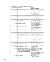
....1-P1-C1 Ignore all location codes. Go to 85. Primary I /O backplane Location: U0.1-P1 1. Table 4. Ensure that the processor assembly(s) are the correct type for proper installation of DIMMs and memory cards 1. Primary I /O backplane Location: U0.1-P1 1. Inspect system memory for the system and...and run CEC minimum configuration. Go to 85. Set the I /O type to MAP 1540 and run CEC minimum configuration. Set the I /O type not recognized 1011 8413 Invalid processor VPD 1011 8423 No processor VPD 1011 8430 V/S Comm cable not connected Action/ Possible Failing FRU ...
....1-P1-C1 Ignore all location codes. Go to 85. Primary I /O backplane Location: U0.1-P1 1. Table 4. Ensure that the processor assembly(s) are the correct type for proper installation of DIMMs and memory cards 1. Primary I /O backplane Location: U0.1-P1 1. Inspect system memory for the system and...and run CEC minimum configuration. Go to 85. Set the I /O type to MAP 1540 and run CEC minimum configuration. Set the I /O type not recognized 1011 8413 Invalid processor VPD 1011 8423 No processor VPD 1011 8430 V/S Comm cable not connected Action/ Possible Failing FRU ...

Service Guide
Page 199
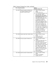
... SPCN cables in time 1011 9102 Permanent address assignment failed Action/ Possible Failing FRU 1. Call service support. 1. Error Code to service processor in the CEC drawer Location: U1.1 2. See Power Control Network Utilities Menu on page 389. 3. Set the I /O backplane Location... 2. Informational only Update system firmware Primary I/O backplane Location: U0.1-P1 Primary I/O backplane Location: U0.1-P1 Primary I /O type to 85. Check for system firmware update. 2. Primary I/O backplane Location: U0.1-P1 Check cabling Primary I/O backplane Location: U0.1-P1 Primary...
... SPCN cables in time 1011 9102 Permanent address assignment failed Action/ Possible Failing FRU 1. Call service support. 1. Error Code to service processor in the CEC drawer Location: U1.1 2. See Power Control Network Utilities Menu on page 389. 3. Set the I /O backplane Location... 2. Informational only Update system firmware Primary I/O backplane Location: U0.1-P1 Primary I/O backplane Location: U0.1-P1 Primary I /O type to 85. Check for system firmware update. 2. Primary I/O backplane Location: U0.1-P1 Check cabling Primary I/O backplane Location: U0.1-P1 Primary...

Service Guide
Page 270
... IPL test detected memory DIMM fault Memory DIMM Location: U1.1-P1-C1-M4 x2 406C 03FF IPL detected memory on processor card fault Memory failure on processor card that the correct type of processor card is plugged into the system, this error occurs on page 113, and run CEC drawer minimum configuration for further...
... IPL test detected memory DIMM fault Memory DIMM Location: U1.1-P1-C1-M4 x2 406C 03FF IPL detected memory on processor card fault Memory failure on processor card that the correct type of processor card is plugged into the system, this error occurs on page 113, and run CEC drawer minimum configuration for further...

Service Guide
Page 374
..." on page 113. 356 Service Guide Update system firmware 2. The specific type and model. Update system firmware 2. Retry flash update 2. B1xx 4600 Service processor failure Primary I /O drawer backplane Location: U0.1-P1 B10F 1681 Service processor firmware update invalid Call service support B10F 1682 Service processor firmware update invalid Call service support B10F 1683 Service...
..." on page 113. 356 Service Guide Update system firmware 2. The specific type and model. Update system firmware 2. Retry flash update 2. B1xx 4600 Service processor failure Primary I /O drawer backplane Location: U0.1-P1 B10F 1681 Service processor firmware update invalid Call service support B10F 1682 Service processor firmware update invalid Call service support B10F 1683 Service...
Service Guide
Page 376
...persists, check the error logs for instructions on reprogramming the machine type, model, and system serial number in the VPD module. B1xx 4647 The machine type and model Replace the operator panel, location: reported by the service processor. If no other fault indications. Common Firmware Error Codes (continued... on the onto the new operator panel; B1xx 4651 CPU VPD fault Processor card Location: U1.1-P1-C1 358 Service Guide Go to recover operations. Do not swap the VPD match the machine type and model module from the old operator panel stored in an attempt to...
...persists, check the error logs for instructions on reprogramming the machine type, model, and system serial number in the VPD module. B1xx 4647 The machine type and model Replace the operator panel, location: reported by the service processor. If no other fault indications. Common Firmware Error Codes (continued... on the onto the new operator panel; B1xx 4651 CPU VPD fault Processor card Location: U1.1-P1-C1 358 Service Guide Go to recover operations. Do not swap the VPD match the machine type and model module from the old operator panel stored in an attempt to...
Service Guide
Page 379
... firmware to "Firmware Checkpoints" on page 382. If no location code is option 1 in the VPD module may be viewed using the service processor function ″Read VPD Image from Last System Boot″, which is specified, and you have an 8-character error code, go to service... processor interface failure) 1. The type and model field in the "System Information Menu" on page 147 3. Table 8. If a location code displays with the error code or checkpoint ...
... firmware to "Firmware Checkpoints" on page 382. If no location code is option 1 in the VPD module may be viewed using the service processor function ″Read VPD Image from Last System Boot″, which is specified, and you have an 8-character error code, go to service... processor interface failure) 1. The type and model field in the "System Information Menu" on page 147 3. Table 8. If a location code displays with the error code or checkpoint ...

Service Guide
Page 380
...firmware update 2. The activating the pinhole reset switch or update was aborted before any by the update image is invalid. B1xx 4699 Service processor firmware 1. Check for system firmware update 2. Primary I /O interface 1. Table 8. Check for system firmware update. 2. B1xx 4698 ..." on page 113, CEC minimum config 3. update image for system firmware update. 2. Call service support. Check for the specific system type and model. 362 Service Guide Call service support. Go to "MAP 1540: Minimum Configuration" on page 113, CEC minimum config 3. ...
...firmware update 2. The activating the pinhole reset switch or update was aborted before any by the update image is invalid. B1xx 4699 Service processor firmware 1. Check for system firmware update 2. Primary I /O interface 1. Table 8. Check for system firmware update. 2. B1xx 4698 ..." on page 113, CEC minimum config 3. update image for system firmware update. 2. Call service support. Check for the specific system type and model. 362 Service Guide Call service support. Go to "MAP 1540: Minimum Configuration" on page 113, CEC minimum config 3. ...

Service Guide
Page 381
...firmware update diskettes. Replace the diskette drive. 3. Location: U0.1-P1 B1FD 001A Service processor recovery mode update fault Reset service processor (by activating pinhole reset switch or by disconnecting, then reconnecting power) B1FD 001E Service processor recovery mode update fault Wrong firmware update diskette (Insert correct diskette) B1FD 001F Bad firmware...diskette may reboot, depending on the reboot policy settings. Try another diskette. 2. When the scan log dump is correct for the specific system type and model 2. Chapter 5. B1FD 0016 Diskette read error 1.
...firmware update diskettes. Replace the diskette drive. 3. Location: U0.1-P1 B1FD 001A Service processor recovery mode update fault Reset service processor (by activating pinhole reset switch or by disconnecting, then reconnecting power) B1FD 001E Service processor recovery mode update fault Wrong firmware update diskette (Insert correct diskette) B1FD 001F Bad firmware...diskette may reboot, depending on the reboot policy settings. Try another diskette. 2. When the scan log dump is correct for the specific system type and model 2. Chapter 5. B1FD 0016 Diskette read error 1.

Service Guide
Page 395
... port snooping is correctly configured, at any point after the reset string is not required, so make sure that the string is complete, the service processor reboots. They are as a ″catch-all″ reset device. System firmware - SERIAL PORT SNOOP SETUP MENU 1. Note: Only serial port 1 ... is booted to set up serial port snooping, in which resets the machine when it is typed on the main console, the system unit reboots. From the service processor main menu, select option 1, Service Processor Setup Menu, then select option 8 (Serial Port Snoop Setup Menu). v Reprogram Flash EPROM...
... port snooping is correctly configured, at any point after the reset string is not required, so make sure that the string is complete, the service processor reboots. They are as a ″catch-all″ reset device. System firmware - SERIAL PORT SNOOP SETUP MENU 1. Note: Only serial port 1 ... is booted to set up serial port snooping, in which resets the machine when it is typed on the main console, the system unit reboots. From the service processor main menu, select option 1, Service Processor Setup Menu, then select option 8 (Serial Port Snoop Setup Menu). v Reprogram Flash EPROM...

Service Guide
Page 402
... fail the boot testing, they remain online. Select Technical Publications. Type the number of this menu is shown below: MEMORY CONFIGURATION/DECONFIGURATION MENU 77. Run-time non-recoverable failure 3. The failure history of each processor is indicated by disabling Repeat Gard, it remains online if it passes... Web address: http://www-1.ibm.com/servers/aix/library/. CPU Repeat Gard is plugged that the CPU has not had any errors logged against it is brought back online by AB, where B indicates the number of errors and A indicates the type of error according to take...
... fail the boot testing, they remain online. Select Technical Publications. Type the number of this menu is shown below: MEMORY CONFIGURATION/DECONFIGURATION MENU 77. Run-time non-recoverable failure 3. The failure history of each processor is indicated by disabling Repeat Gard, it remains online if it passes... Web address: http://www-1.ibm.com/servers/aix/library/. CPU Repeat Gard is plugged that the CPU has not had any errors logged against it is brought back online by AB, where B indicates the number of errors and A indicates the type of error according to take...

Service Guide
Page 403
...In that processor assembly. Using the Service Processor 385 ...reside on a processor card, pair ...processor card or a memory riser card, a menu allowing the selection of error according to select the processor... card from vital product data collected during the next boot into AIX. The fields in the diagrams "Memory Riser Card 1 Memory DIMM Locations for Service Processor...Processor Menus" on page 387 and "Processor Card Memory DIMM Locations for Service Processor Menus" on page 388. Bring-up , or after the system's non-volatile RAM...2 (3.xx) Memory on processor card Column 3 (00...
...In that processor assembly. Using the Service Processor 385 ...reside on a processor card, pair ...processor card or a memory riser card, a menu allowing the selection of error according to select the processor... card from vital product data collected during the next boot into AIX. The fields in the diagrams "Memory Riser Card 1 Memory DIMM Locations for Service Processor...Processor Menus" on page 387 and "Processor Card Memory DIMM Locations for Service Processor Menus" on page 388. Bring-up , or after the system's non-volatile RAM...2 (3.xx) Memory on processor card Column 3 (00...

Service Guide
Page 407
Display I /O drawer operator panel. Indicators come on and stay on the primary I /O Type 3. Nothing displays on for the secondary I /O type is incorrect. Using the Service Processor 389 POWER CONTROL NETWORK UTILITIES MENU 1. Return to change the I/O type of the primary I/O drawer or secondary I/O drawer after a service action or configuration change the I /O drawer. - 84 for approximately...
Display I /O drawer operator panel. Indicators come on and stay on the primary I /O Type 3. Nothing displays on for the secondary I /O type is incorrect. Using the Service Processor 389 POWER CONTROL NETWORK UTILITIES MENU 1. Return to change the I/O type of the primary I/O drawer or secondary I/O drawer after a service action or configuration change the I /O drawer. - 84 for approximately...

Service Guide
Page 417
...-on or upon reboot after a system failure, the service processor monitors the boot progress. Using the Service Processor 399 Restart describes activating the operating system after a hardware or surveillance failure. If you can select the IPL type, mode, and speed of retries that has been set in... the Reboot/Restart Policy Setup Menu. Attention: Selecting fast IPL results in the Service Processor Reboot/Restart Policy Setup Menu and the OS automatic restart settings...
...-on or upon reboot after a system failure, the service processor monitors the boot progress. Using the Service Processor 399 Restart describes activating the operating system after a hardware or surveillance failure. If you can select the IPL type, mode, and speed of retries that has been set in... the Reboot/Restart Policy Setup Menu. Attention: Selecting fast IPL results in the Service Processor Reboot/Restart Policy Setup Menu and the OS automatic restart settings...

