Hardware Maintenance Manual
Page 68
... 1 Translations in ″Safety Notices (Multi-lingual Translations)″ section: Before the computer is powered-on page 98 for rattling sounds. Do not disassemble it, throw it into fire or water, or short-circuit it. v The arrows in ″Safety Notices (Multi-lingual Translations)″ section: ..." on after FRU replacement, make sure all screws, springs, or other small parts are listed at the top of the battery. 62 ThinkPad R32 Series Verify this section show the correct sequence of the battery pack as shown in the appropriate parts listing when replacing the battery pack....
... 1 Translations in ″Safety Notices (Multi-lingual Translations)″ section: Before the computer is powered-on page 98 for rattling sounds. Do not disassemble it, throw it into fire or water, or short-circuit it. v The arrows in ″Safety Notices (Multi-lingual Translations)″ section: ..." on after FRU replacement, make sure all screws, springs, or other small parts are listed at the top of the battery. 62 ThinkPad R32 Series Verify this section show the correct sequence of the battery pack as shown in the appropriate parts listing when replacing the battery pack....
Hardware Maintenance Manual
Page 69
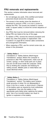
.... An electrostatic discharge (ESD) strap (P/N: 6405959) must be revervsed, for instance, 4, 3, 2, 1d, 1c, 1b, 1a. 1010 Battery Disassembly 1 22 Warning Battery packs are capable of delivering high currents for a significant amount of time. Please note that when you assemble the computer, the... pack, then disconnect any interconnecting cables. Dispose of explosion if battery is sensitive and can be damaged by the manufacturer. MT 2658/2659/2677 63 CAUTION: Danger of used to the manufacturer's instructions. Attention: The system board is incorrectly replaced. Do not ...
.... An electrostatic discharge (ESD) strap (P/N: 6405959) must be revervsed, for instance, 4, 3, 2, 1d, 1c, 1b, 1a. 1010 Battery Disassembly 1 22 Warning Battery packs are capable of delivering high currents for a significant amount of time. Please note that when you assemble the computer, the... pack, then disconnect any interconnecting cables. Dispose of explosion if battery is sensitive and can be damaged by the manufacturer. MT 2658/2659/2677 63 CAUTION: Danger of used to the manufacturer's instructions. Attention: The system board is incorrectly replaced. Do not ...
Hardware Maintenance Manual
Page 70
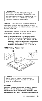
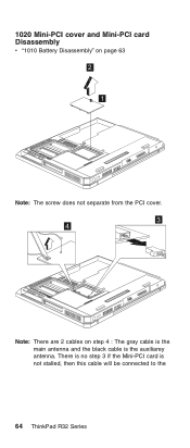
There is no step 3 if the Mini-PCI card is the auxiliarey antenna. 1020 Mini-PCI cover and Mini-PCI card Disassembly v "1010 Battery Disassembly" on page 63 2 1 Note: The screw does not separate from the PCI cover. 3 3 4 Note: There are 2 cables on step 4 : The gray cable is the main antenna and the black cable is not stalled, then this cable will be connected to the 64 ThinkPad R32 Series
There is no step 3 if the Mini-PCI card is the auxiliarey antenna. 1020 Mini-PCI cover and Mini-PCI card Disassembly v "1010 Battery Disassembly" on page 63 2 1 Note: The screw does not separate from the PCI cover. 3 3 4 Note: There are 2 cables on step 4 : The gray cable is the main antenna and the black cable is not stalled, then this cable will be connected to the 64 ThinkPad R32 Series

Hardware Maintenance Manual
Page 71
CDC card. Note: When you install the PCI card, remember to insert it into its socket at 20°, press it down and ensure the connection is well. 1030 Memory cover and Memory card Disassembly v "1010 Battery Disassembly" on page 63 2 1 MT 2658/2659/2677 65
CDC card. Note: When you install the PCI card, remember to insert it into its socket at 20°, press it down and ensure the connection is well. 1030 Memory cover and Memory card Disassembly v "1010 Battery Disassembly" on page 63 2 1 MT 2658/2659/2677 65

Hardware Maintenance Manual
Page 72
Pivot the memory card until it firmly. Note: The screws do not separate from the memory cover. 2 1 To install the memory card: With the notched end of the memory card toward the right side of the socket, insert the memory card, at an angle of approximately 20°, into place. Side View 1040 Hard Disk Drive Disassembly v "1010 Battery Disassembly" on page 63 66 ThinkPad R32 Series then press it snaps into the socket;
Pivot the memory card until it firmly. Note: The screws do not separate from the memory cover. 2 1 To install the memory card: With the notched end of the memory card toward the right side of the socket, insert the memory card, at an angle of approximately 20°, into place. Side View 1040 Hard Disk Drive Disassembly v "1010 Battery Disassembly" on page 63 66 ThinkPad R32 Series then press it snaps into the socket;

Hardware Maintenance Manual
Page 73
... the hard disk drive. The hard disk drive is in suspend mode. 1050 Hard Disk Drive Cover Disassembly v "1010 Battery Disassembly" on page 63 1 1060 CD-ROM Disassembly v "1010 Battery Disassembly" on the drive. Incorrect handling can cause damage and permanent loss of all the information on the... drive if possible. Before removing the drive, have the user make a backup copy of data on page 63 MT 2658/2659/2677 67 1 2 ...
... the hard disk drive. The hard disk drive is in suspend mode. 1050 Hard Disk Drive Cover Disassembly v "1010 Battery Disassembly" on page 63 1 1060 CD-ROM Disassembly v "1010 Battery Disassembly" on the drive. Incorrect handling can cause damage and permanent loss of all the information on the... drive if possible. Before removing the drive, have the user make a backup copy of data on page 63 MT 2658/2659/2677 67 1 2 ...

Hardware Maintenance Manual
Page 74
1 2 3 1070 Keyboard Disassembly v "1010 Battery Disassembly" on page 63 1a 1b Step 1 Size (Quantity) M2.5 x L10 (2) Color Black 68 ThinkPad R32 Series Torque 3.2 kgf-cm
1 2 3 1070 Keyboard Disassembly v "1010 Battery Disassembly" on page 63 1a 1b Step 1 Size (Quantity) M2.5 x L10 (2) Color Black 68 ThinkPad R32 Series Torque 3.2 kgf-cm

Hardware Maintenance Manual
Page 75
Be careful when pulling out the cable. 1080 Backup Battery Disassembly v "1010 Battery Disassembly" on page 63 v "1070 Keyboard Disassembly" on page 68 MT 2658/2659/2677 69 The cable of the connector, the keyboard function will be damaged. If the cable do not touch the bottom of the keyboard are fragile and could be rendered useless. 3. When replacing the keyboard, make sure that the cable is clean and insert it directly into the connector, making sure it makes contact with the bottom of the connector. 2. 2 4 3 Notes: 1.
Be careful when pulling out the cable. 1080 Backup Battery Disassembly v "1010 Battery Disassembly" on page 63 v "1070 Keyboard Disassembly" on page 68 MT 2658/2659/2677 69 The cable of the connector, the keyboard function will be damaged. If the cable do not touch the bottom of the keyboard are fragile and could be rendered useless. 3. When replacing the keyboard, make sure that the cable is clean and insert it directly into the connector, making sure it makes contact with the bottom of the connector. 2. 2 4 3 Notes: 1.
Hardware Maintenance Manual
Page 76
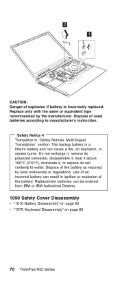
...only with the same or equivalent type recommended by local ordinances or regulations. Do not recharge it, remove its polarized connector, disassemble it, heat it above 100°C (212°F), incinerate it, or expose its cell contents to manufacturer's instruction. ... Translation in ignition or explosion of the battery as required by the manufacturer. Replacement batteries can be ordered from IBM or IBM Authorized Dealers. 1090 Safety Cover Disassembly v "1010 Battery Disassembly" on page 63 v "1070 Keyboard Disassembly" on page 68 70 ThinkPad R32 Series Dispose of the battery.
...only with the same or equivalent type recommended by local ordinances or regulations. Do not recharge it, remove its polarized connector, disassemble it, heat it above 100°C (212°F), incinerate it, or expose its cell contents to manufacturer's instruction. ... Translation in ignition or explosion of the battery as required by the manufacturer. Replacement batteries can be ordered from IBM or IBM Authorized Dealers. 1090 Safety Cover Disassembly v "1010 Battery Disassembly" on page 63 v "1070 Keyboard Disassembly" on page 68 70 ThinkPad R32 Series Dispose of the battery.
Hardware Maintenance Manual
Page 78
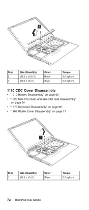
4 Step 2 4 Size (Quantity) M2.5 x L10 (1) M2.5 x L5 (1) Color Black Silver Torque 3.2 kgf-cm 2.5 kgf-cm 1110 CDC Cover Disassembly v "1010 Battery Disassembly" on page 63 v "1020 Mini-PCI cover and Mini-PCI card Disassembly" on page 64 v "1070 Keyboard Disassembly" on page 68 v "1100 Middle Cover Disassembly" on page 71 1 Step 1 Size (Quantity) M2.5 x L5 (1) Color Silver Torque 2.5 kgf-cm 72 ThinkPad R32 Series
4 Step 2 4 Size (Quantity) M2.5 x L10 (1) M2.5 x L5 (1) Color Black Silver Torque 3.2 kgf-cm 2.5 kgf-cm 1110 CDC Cover Disassembly v "1010 Battery Disassembly" on page 63 v "1020 Mini-PCI cover and Mini-PCI card Disassembly" on page 64 v "1070 Keyboard Disassembly" on page 68 v "1100 Middle Cover Disassembly" on page 71 1 Step 1 Size (Quantity) M2.5 x L5 (1) Color Silver Torque 2.5 kgf-cm 72 ThinkPad R32 Series
Hardware Maintenance Manual
Page 79
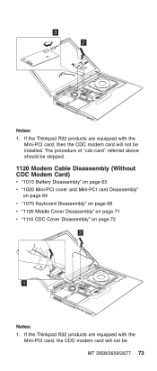
...MT 2658/2659/2677 73 If the Thinkpad R32 products are equipped with the Mini-PCI card, the CDC modem card will not be installed. 3 2 Notes: 1. If the Thinkpad R32 products are equipped with the Mini-PCI card, then the CDC modem card will not be skipped. 1120 Modem Cable Disassembly (Without... CDC Modem Card) v "1010 Battery Disassembly" on page 63 v "1020 Mini-PCI cover and Mini-PCI card...
...MT 2658/2659/2677 73 If the Thinkpad R32 products are equipped with the Mini-PCI card, the CDC modem card will not be installed. 3 2 Notes: 1. If the Thinkpad R32 products are equipped with the Mini-PCI card, then the CDC modem card will not be skipped. 1120 Modem Cable Disassembly (Without... CDC Modem Card) v "1010 Battery Disassembly" on page 63 v "1020 Mini-PCI cover and Mini-PCI card...
Hardware Maintenance Manual
Page 80
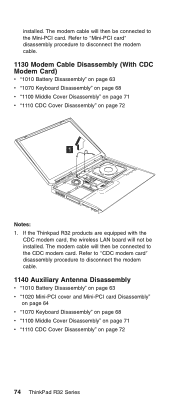
...: 1. Refer to ″CDC modem card″ disassembly procedure to disconnect the modem cable. 1130 Modem Cable Disassembly (With CDC Modem Card) v "1010 Battery Disassembly" on page 63 v "1070 Keyboard Disassembly" on page 68 v "1100 Middle Cover Disassembly" on page 71 v "1110 CDC Cover Disassembly" on page 72 74 ThinkPad R32 Series The modem cable will then be...
...: 1. Refer to ″CDC modem card″ disassembly procedure to disconnect the modem cable. 1130 Modem Cable Disassembly (With CDC Modem Card) v "1010 Battery Disassembly" on page 63 v "1070 Keyboard Disassembly" on page 68 v "1100 Middle Cover Disassembly" on page 71 v "1110 CDC Cover Disassembly" on page 72 74 ThinkPad R32 Series The modem cable will then be...

Hardware Maintenance Manual
Page 81
2 1 Step 2 Size (Quantity) M2 x L2.5(1) Color Silver Torque 2.0 kgf-cm Note: Release the black cable, which is the auxiliary antenna from the system. 1150 Auxiliary Antenna Reassembly v "1010 Battery Disassembly" on page 63 v "1020 Mini-PCI cover and Mini-PCI card Disassembly" on page 64 v "1070 Keyboard Disassembly" on page 68 v "1100 Middle Cover Disassembly" on page 71 v "1110 CDC Cover Disassembly" on page 72 MT 2658/2659/2677 75
2 1 Step 2 Size (Quantity) M2 x L2.5(1) Color Silver Torque 2.0 kgf-cm Note: Release the black cable, which is the auxiliary antenna from the system. 1150 Auxiliary Antenna Reassembly v "1010 Battery Disassembly" on page 63 v "1020 Mini-PCI cover and Mini-PCI card Disassembly" on page 64 v "1070 Keyboard Disassembly" on page 68 v "1100 Middle Cover Disassembly" on page 71 v "1110 CDC Cover Disassembly" on page 72 MT 2658/2659/2677 75

Hardware Maintenance Manual
Page 82
3 1 2 Note: Please follow number 1, 2, 3 to reintsall the auxiliary antenna and arrange the cable well based on the above drawing. 1160 Coaxial Cable and Inverter Cable Disassembly v "1010 Battery Disassembly" on page 63 v "1020 Mini-PCI cover and Mini-PCI card Disassembly" on page 64 v "1070 Keyboard Disassembly" on page 68 v "1100 Middle Cover Disassembly" on page 71 v "1110 CDC Cover Disassembly" on page 72 1a 1b 76 ThinkPad R32 Series
3 1 2 Note: Please follow number 1, 2, 3 to reintsall the auxiliary antenna and arrange the cable well based on the above drawing. 1160 Coaxial Cable and Inverter Cable Disassembly v "1010 Battery Disassembly" on page 63 v "1020 Mini-PCI cover and Mini-PCI card Disassembly" on page 64 v "1070 Keyboard Disassembly" on page 68 v "1100 Middle Cover Disassembly" on page 71 v "1110 CDC Cover Disassembly" on page 72 1a 1b 76 ThinkPad R32 Series

Hardware Maintenance Manual
Page 83
Step 1 Size (Quantity) M2.5 x L5 (2) Color Silver 3 Torque 2.5 kgf-cm 2 4 Note: Release the gray cable, which is the main antenna from the system. 1170 LCD Disassembly v "1010 Battery Disassembly" on page 63 v "1020 Mini-PCI cover and Mini-PCI card Disassembly" on page 64 v "1070 Keyboard Disassembly" on page 68 v "1100 Middle Cover Disassembly" on page 71 v "1110 CDC Cover Disassembly" on page 72 MT 2658/2659/2677 77
Step 1 Size (Quantity) M2.5 x L5 (2) Color Silver 3 Torque 2.5 kgf-cm 2 4 Note: Release the gray cable, which is the main antenna from the system. 1170 LCD Disassembly v "1010 Battery Disassembly" on page 63 v "1020 Mini-PCI cover and Mini-PCI card Disassembly" on page 64 v "1070 Keyboard Disassembly" on page 68 v "1100 Middle Cover Disassembly" on page 71 v "1110 CDC Cover Disassembly" on page 72 MT 2658/2659/2677 77

Hardware Maintenance Manual
Page 84
1c 1b 1d 1a Step 1 Size (Quantity) M2.5 x L10 (4) Color Black Torque 3.2 kgf-cm 2 1180 Keyboard bezel Disassembly v "1010 Battery Disassembly" on page 63 v "1020 Mini-PCI cover and Mini-PCI card Disassembly" on page 64 v "1040 Hard Disk Drive Disassembly" on page 66 v "1070 Keyboard Disassembly" on page 68 v "1100 Middle Cover Disassembly" on page 71 v "1170 LCD Disassembly" on page 77 78 ThinkPad R32 Series
1c 1b 1d 1a Step 1 Size (Quantity) M2.5 x L10 (4) Color Black Torque 3.2 kgf-cm 2 1180 Keyboard bezel Disassembly v "1010 Battery Disassembly" on page 63 v "1020 Mini-PCI cover and Mini-PCI card Disassembly" on page 64 v "1040 Hard Disk Drive Disassembly" on page 66 v "1070 Keyboard Disassembly" on page 68 v "1100 Middle Cover Disassembly" on page 71 v "1170 LCD Disassembly" on page 77 78 ThinkPad R32 Series

Hardware Maintenance Manual
Page 86
... v "1040 Hard Disk Drive Disassembly" on page 66 v "1070 Keyboard Disassembly" on page 68 v "1090 Safety Cover Disassembly" on page 70 v "1100 Middle Cover Disassembly" on page 71 v "1170 LCD Disassembly" on page 77 v "1160 Coaxial Cable and Inverter Cable Disassembly" on page 76 v "1180 Keyboard bezel Disassembly" on page 78 80 ThinkPad R32 Series Be careful not to...
... v "1040 Hard Disk Drive Disassembly" on page 66 v "1070 Keyboard Disassembly" on page 68 v "1090 Safety Cover Disassembly" on page 70 v "1100 Middle Cover Disassembly" on page 71 v "1170 LCD Disassembly" on page 77 v "1160 Coaxial Cable and Inverter Cable Disassembly" on page 76 v "1180 Keyboard bezel Disassembly" on page 78 80 ThinkPad R32 Series Be careful not to...

Hardware Maintenance Manual
Page 87
1 Step 1 Size (Quantity) M2.5 x L5 (1) Color Silver Torque 2.5 kgf-cm 1200 PCMCIA Holder Disassembly v "1010 Battery Disassembly" on page 63 v "1070 Keyboard Disassembly" on page 68 v "1030 Memory cover and Memory card Disassembly" on page 65 1 MT 2658/2659/2677 81
1 Step 1 Size (Quantity) M2.5 x L5 (1) Color Silver Torque 2.5 kgf-cm 1200 PCMCIA Holder Disassembly v "1010 Battery Disassembly" on page 63 v "1070 Keyboard Disassembly" on page 68 v "1030 Memory cover and Memory card Disassembly" on page 65 1 MT 2658/2659/2677 81

Hardware Maintenance Manual
Page 88
2b 2a 2d 2c Step 2 Size (Quantity) M2 x L6 (4) Color Silver 3 Torque 1.6 kgf-cm Note: Before removing and replacing the PCMCIA holder, make sure that the PCMCIA cards are removed and the eject levers are sticking out. 1210 Heat Sink Module Disassembly v "1010 Battery Disassembly" on page 63 v "1070 Keyboard Disassembly" on page 68 v "1100 Middle Cover Disassembly" on page 71 82 ThinkPad R32 Series
2b 2a 2d 2c Step 2 Size (Quantity) M2 x L6 (4) Color Silver 3 Torque 1.6 kgf-cm Note: Before removing and replacing the PCMCIA holder, make sure that the PCMCIA cards are removed and the eject levers are sticking out. 1210 Heat Sink Module Disassembly v "1010 Battery Disassembly" on page 63 v "1070 Keyboard Disassembly" on page 68 v "1100 Middle Cover Disassembly" on page 71 82 ThinkPad R32 Series

Hardware Maintenance Manual
Page 89
Thermal Pad is replaced. Do not re-use the thermal pad. 1220 Fan Disassembly v "1010 Battery Disassembly" on page 63 v "1070 Keyboard Disassembly" on page 68 v "1100 Middle Cover Disassembly" on the bottom side of Heat Sink Module with adhesive. 1a 1c 1b 1d 1 Step 1 Size (Quantity) CPU Special Screw(4) Color Silver Torque 2.5 kgf-cm Note: Thermal Pad must be replaced when either Heat Sink Module, CPU or System Board is stuck on page 71 MT 2658/2659/2677 83
Thermal Pad is replaced. Do not re-use the thermal pad. 1220 Fan Disassembly v "1010 Battery Disassembly" on page 63 v "1070 Keyboard Disassembly" on page 68 v "1100 Middle Cover Disassembly" on the bottom side of Heat Sink Module with adhesive. 1a 1c 1b 1d 1 Step 1 Size (Quantity) CPU Special Screw(4) Color Silver Torque 2.5 kgf-cm Note: Thermal Pad must be replaced when either Heat Sink Module, CPU or System Board is stuck on page 71 MT 2658/2659/2677 83