Owner's Manual
Page 1
Installation Guide ENGLISH See page 2 Español Vea la página 21 90052/90053/90054/90058 Saturn™ Bath Ventilator with Light READ and SAVE THESE INSTRUCTIONS 028_41718_EngS_1.28.08_Arial.indd 1 1 41718-01 01/28/2008 1/28/08 10:47:06 AM
Installation Guide ENGLISH See page 2 Español Vea la página 21 90052/90053/90054/90058 Saturn™ Bath Ventilator with Light READ and SAVE THESE INSTRUCTIONS 028_41718_EngS_1.28.08_Arial.indd 1 1 41718-01 01/28/2008 1/28/08 10:47:06 AM
Owner's Manual
Page 2
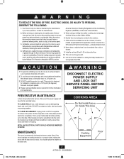
...are making excessive or unusual noises, replace the motor with all applicable codes and standards, including fire-rated construction. 4. COOKING AREA Do Not Install Above Or Inside This Area 45° 45° Cooking Equipment Floor 2 41718-01 01/28/2008 028_41718_EngS_1.28.08_Arial.indd 2 1/... qualified person(s) in the housing (next to tab) and twist screwdriver. Never place a switch where it must not be connected to be installed over a tub or shower, it can be reached from receptacle. To avoid motor bearing damage and noisy/unbalanced impellers, keep drywall spray, ...
...are making excessive or unusual noises, replace the motor with all applicable codes and standards, including fire-rated construction. 4. COOKING AREA Do Not Install Above Or Inside This Area 45° 45° Cooking Equipment Floor 2 41718-01 01/28/2008 028_41718_EngS_1.28.08_Arial.indd 2 1/... qualified person(s) in the housing (next to tab) and twist screwdriver. Never place a switch where it must not be connected to be installed over a tub or shower, it can be reached from receptacle. To avoid motor bearing damage and noisy/unbalanced impellers, keep drywall spray, ...
Owner's Manual
Page 3
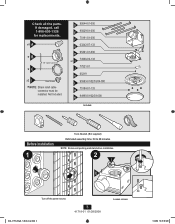
D 95044-01-000 E 95029-01-000 F 75191-01-000 G 03242-07-133 H 95491-01-000 x2 I Extra Screws * NOTE: Strain relief cable connector must be installed. x4 A *B *C 3/8" Cable Connector x2 I 74508-03-133 J 77521-01 K 65219 L 95583-01/02/03/04-000 M 75184-01-133 N 94990-01/02/...03-000 Included. Before Installation 1 Tools Needed. (Not supplied) Estimated assembly time: 30 to 60 minutes NOTE: Remove all the parts. If damaged, call 1-888-830-1326 for replacements. Not...
D 95044-01-000 E 95029-01-000 F 75191-01-000 G 03242-07-133 H 95491-01-000 x2 I Extra Screws * NOTE: Strain relief cable connector must be installed. x4 A *B *C 3/8" Cable Connector x2 I 74508-03-133 J 77521-01 K 65219 L 95583-01/02/03/04-000 M 75184-01-133 N 94990-01/02/...03-000 Included. Before Installation 1 Tools Needed. (Not supplied) Estimated assembly time: 30 to 60 minutes NOTE: Remove all the parts. If damaged, call 1-888-830-1326 for replacements. Not...
Owner's Manual
Page 5
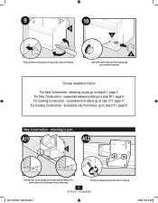
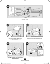
.../28/2008 028_41718_EngS_1.28.08_Arial.indd 5 1/28/08 10:47:13 AM accessible only from above go to step A11, page 5 For New Construction - Choose Installation Option For New Construction - 9 10 E C Pop out the first wiring access slug. suspended between joists go to step D11, page15 New Construction - Use second if...
.../28/2008 028_41718_EngS_1.28.08_Arial.indd 5 1/28/08 10:47:13 AM accessible only from above go to step A11, page 5 For New Construction - Choose Installation Option For New Construction - 9 10 E C Pop out the first wiring access slug. suspended between joists go to step D11, page15 New Construction - Use second if...
Owner's Manual
Page 6
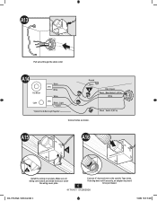
... outside. Connect 4" duct and vent to be purchased. 6 41718-01 01/28/2008 028_41718_EngS_1.28.08_Arial.indd 6 1/28/08 10:47:15 AM A15 A016 E G Install the wiring cover plate. Make sure all wiring connections are inside the box or under the wiring cover plate. A13 Pull wires through the strain...
... outside. Connect 4" duct and vent to be purchased. 6 41718-01 01/28/2008 028_41718_EngS_1.28.08_Arial.indd 6 1/28/08 10:47:15 AM A15 A016 E G Install the wiring cover plate. Make sure all wiring connections are inside the box or under the wiring cover plate. A13 Pull wires through the strain...
Owner's Manual
Page 9
... *Option Fan & Main Light Together Ground Green A Bare Copper Black Main Switch 1 (AC In) White Black Switch 2 (AC In) Connect wires as shown. B20 B21 F G Install the wiring cover plate.
... *Option Fan & Main Light Together Ground Green A Bare Copper Black Main Switch 1 (AC In) White Black Switch 2 (AC In) Connect wires as shown. B20 B21 F G Install the wiring cover plate.
Owner's Manual
Page 13
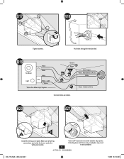
Make sure all wiring connections are inside the box or under the wiring cover plate. 13 41718-01 01/28/2008 Connect wiring from the motor to the wiring cover plate. 028_41718_EngS_1.28.08_Arial.indd 13 1/28/08 10:47:35 AM C22 Fan Motor Light Black 2 Pin White White 3 Pin Black Light *Option *Option Fan & Main Light Together Ground Green A Bare Copper Black Main Switch 1 (AC In) White Black Switch 2 (AC In) Connect wires as shown. C21 Tighten the strain relief screws. C23 C24 F H G Install the wiring cover plate.
Make sure all wiring connections are inside the box or under the wiring cover plate. 13 41718-01 01/28/2008 Connect wiring from the motor to the wiring cover plate. 028_41718_EngS_1.28.08_Arial.indd 13 1/28/08 10:47:35 AM C22 Fan Motor Light Black 2 Pin White White 3 Pin Black Light *Option *Option Fan & Main Light Together Ground Green A Bare Copper Black Main Switch 1 (AC In) White Black Switch 2 (AC In) Connect wires as shown. C21 Tighten the strain relief screws. C23 C24 F H G Install the wiring cover plate.
Owner's Manual
Page 16
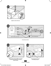
D17 D18 F G Install the wiring cover plate. Make sure all wiring connections are not pinched between the motor and the housing. 16 Secure the motor by inserting the ...
D17 D18 F G Install the wiring cover plate. Make sure all wiring connections are not pinched between the motor and the housing. 16 Secure the motor by inserting the ...
Owner's Manual
Page 18
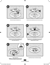
... into motor housing) with posts A, B, C and D (stamped into light fixture). Slide light fixture over the lip of electrical shock, all 4 thumbscrews MUST be properly installed. 18 Install 2 Max 60 watt A-15 bulbs (Not Included). 41718-01 01/28/2008 028_41718_EngS_1.28.08_Arial.indd 18 1/28/08 10:47:48 AM E8 M Attach...
... into motor housing) with posts A, B, C and D (stamped into light fixture). Slide light fixture over the lip of electrical shock, all 4 thumbscrews MUST be properly installed. 18 Install 2 Max 60 watt A-15 bulbs (Not Included). 41718-01 01/28/2008 028_41718_EngS_1.28.08_Arial.indd 18 1/28/08 10:47:48 AM E8 M Attach...
Owner's Manual
Page 20
..., or unreasonable use of parts or accessories not authorized by us, mishandling, improper installation, modifications or damage to the Hunter bath exhaust fan while in Memphis, Tennessee. This warranty is voided if your Hunter bath exhaust fan is required when requesting warranty service. SOME STATES DO NOT ALLOW .... If no replacement part can be responsible for any such damage. Proof of purchase is not purchased and installed in China 20 41718-01 01/28/2008 © 2008 Hunter Fan Company 1/28/08 10:47:50 AM Please contact us before shipping your bath exhaust fan to a...
..., or unreasonable use of parts or accessories not authorized by us, mishandling, improper installation, modifications or damage to the Hunter bath exhaust fan while in Memphis, Tennessee. This warranty is voided if your Hunter bath exhaust fan is required when requesting warranty service. SOME STATES DO NOT ALLOW .... If no replacement part can be responsible for any such damage. Proof of purchase is not purchased and installed in China 20 41718-01 01/28/2008 © 2008 Hunter Fan Company 1/28/08 10:47:50 AM Please contact us before shipping your bath exhaust fan to a...


