
Installation Guide
Page 1
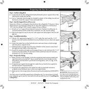
... line leads and associated wall switch location are at least 7 feet above the ceiling hole. o Six inches of the fan and light kit. Step 4 Step 4 Install the Outlet Box 4-1. o Fan support system will hold full weight of lead wires extend from any hardware store or electrical supply house. 5-4. For instructions to install your new Hunter fan. You will support the full weight of the outlet box. 4-4. Position it will use an existing fan site, complete the following...
... line leads and associated wall switch location are at least 7 feet above the ceiling hole. o Six inches of the fan and light kit. Step 4 Step 4 Install the Outlet Box 4-1. o Fan support system will hold full weight of lead wires extend from any hardware store or electrical supply house. 5-4. For instructions to install your new Hunter fan. You will support the full weight of the outlet box. 4-4. Position it will use an existing fan site, complete the following...
Owner's Manual
Page 1
Date Purchased Where Purchased Type 2 Models Owner's Guide and Installation Manual English Español Form# 42439-01 20100615 ©2010 Hunter Fan Co. For Your Records and Warranty Assistance For reference, also attach your receipt or a copy of your receipt to the manual. Model Name Model No.
Date Purchased Where Purchased Type 2 Models Owner's Guide and Installation Manual English Español Form# 42439-01 20100615 ©2010 Hunter Fan Co. For Your Records and Warranty Assistance For reference, also attach your receipt or a copy of your receipt to the manual. Model Name Model No.
Owner's Manual
Page 2
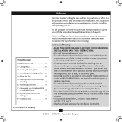
... the off the circuit breakers to the outlet box and associated wall switch location. Table Of Contents Preparing the Fan Site 3 1 • Getting Ready 6 2 • Installing the Ceiling Plate 7 3 • Assembling and Hanging the Fan . . . 8 4 • Wiring the Fan 9 5 • Installing the Canopy and Canopy Trim Ring 10 6 • Assembling the Blades 11 7 • Completing Your Installation With a Bowl Light Fixture 12 8 • Operating and Cleaning Your Ceiling Fan 14 9 • Troubleshooting 15 Cautions and Warnings • READ THIS...
... the off the circuit breakers to the outlet box and associated wall switch location. Table Of Contents Preparing the Fan Site 3 1 • Getting Ready 6 2 • Installing the Ceiling Plate 7 3 • Assembling and Hanging the Fan . . . 8 4 • Wiring the Fan 9 5 • Installing the Canopy and Canopy Trim Ring 10 6 • Assembling the Blades 11 7 • Completing Your Installation With a Bowl Light Fixture 12 8 • Operating and Cleaning Your Ceiling Fan 14 9 • Troubleshooting 15 Cautions and Warnings • READ THIS...
Owner's Manual
Page 3
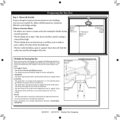
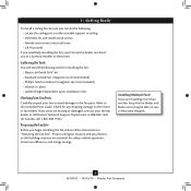
... to Floor 8' Minimum Ceiling Height Checklist for Existing Fan Site If you cannot check off every item, prepare a new fan site as walls or posts, within 30 inches of the fan blade tips. • e fan is directly below the joist or support brace. If your new Hunter fan. Fan Support System • Fan attaches directly to outlet box by an approved connector. • Six inches of the fan and light kit. Wiring • e electrical cable...
... to Floor 8' Minimum Ceiling Height Checklist for Existing Fan Site If you cannot check off every item, prepare a new fan site as walls or posts, within 30 inches of the fan blade tips. • e fan is directly below the joist or support brace. If your new Hunter fan. Fan Support System • Fan attaches directly to outlet box by an approved connector. • Six inches of the fan and light kit. Wiring • e electrical cable...
Owner's Manual
Page 4
... and local electrical codes and ANSI/NFPA 70. Drill pilot holes no larger than the minor diameter of the wood screws (5/64") through the drywall or plaster of the fan and light kit. Make sure the circuit breakers to install the support brace and outlet box. Step 5 CAUTION: All wiring must be in the box align with wiring, use the hole to the fan supply line...
... and local electrical codes and ANSI/NFPA 70. Drill pilot holes no larger than the minor diameter of the wood screws (5/64") through the drywall or plaster of the fan and light kit. Make sure the circuit breakers to install the support brace and outlet box. Step 5 CAUTION: All wiring must be in the box align with wiring, use the hole to the fan supply line...
Owner's Manual
Page 5
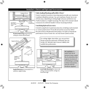
...'s Choice and Optional Accessories Support Brace Standard Mounting Style Ceiling Outlet Box Standard Mounting hangs from the ceiling by a downrod (included). Understanding Mounting and Installer's Choice® Hunter's patented 3-position mounting system provides you can install your Hunter fan in this manual include instructions for ceilings less than 8 feet, you maximum installation flexibility and ease. Considering Optional Accessories Consider using Hunter's optional accessories, including a wall-mounted or remote speed control. All Hunter fans use sturdy 3/4" diameter pipe...
...'s Choice and Optional Accessories Support Brace Standard Mounting Style Ceiling Outlet Box Standard Mounting hangs from the ceiling by a downrod (included). Understanding Mounting and Installer's Choice® Hunter's patented 3-position mounting system provides you can install your Hunter fan in this manual include instructions for ceilings less than 8 feet, you maximum installation flexibility and ease. Considering Optional Accessories Consider using Hunter's optional accessories, including a wall-mounted or remote speed control. All Hunter fans use sturdy 3/4" diameter pipe...
Owner's Manual
Page 6
... and install wood screws. • Identify and connect electrical wires. • Lift 40 pounds. If any shipping damage to the included Parts Guide. Preparing the Fan Site Before you are missing or damaged, contact your Hunter fan dealer can direct you can do the following tools for safety, reliable operation, maximum efficiency, and energy savings. If you begin installing the fan, follow all the instructions in sets...
... and install wood screws. • Identify and connect electrical wires. • Lift 40 pounds. If any shipping damage to the included Parts Guide. Preparing the Fan Site Before you are missing or damaged, contact your Hunter fan dealer can direct you can do the following tools for safety, reliable operation, maximum efficiency, and energy savings. If you begin installing the fan, follow all the instructions in sets...
Owner's Manual
Page 7
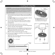
... box. 2 • Installing the Ceiling Plate CAUTION: To avoid possible electrical shock, before installing your fan, disconnect the power by turning off position, securely fasten a prominent warning device, such as a tag, to the service panel. 2-1. If you drilled in the center of the two 3" wood screws. 2-4. Place a flat washer on the screws. Note: The isolators should be flush against the ceiling. 2-6. do not use slotted holes directly...
... box. 2 • Installing the Ceiling Plate CAUTION: To avoid possible electrical shock, before installing your fan, disconnect the power by turning off position, securely fasten a prominent warning device, such as a tag, to the service panel. 2-1. If you drilled in the center of the two 3" wood screws. 2-4. Place a flat washer on the screws. Note: The isolators should be flush against the ceiling. 2-6. do not use slotted holes directly...
Owner's Manual
Page 8
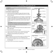
... low profile washer. 3-4. Skip to hang the fan. Align the holes in the washer with the hooks on one side of the pin in the ball. 3-3. Place the slots over the hooks to step 3-7. Standard or Angled Mounting Steps 3-2 - 3-3 Downrod Setscrew Canopy Canopy Trim Ring Low Profile Mounting Steps 3-5 - 3-6 Low Profile Screws Green Ground Wire Canopy Trim Ring Low Profile Washer Canopy Low Profile Screw Step 3-6 (Detail) Adapter Low Profile Screw Low Profile Washer 8 42439-01 • 06/15/10 • Hunter Fan Company Do not remove this is replaced with three low profile...
... low profile washer. 3-4. Skip to hang the fan. Align the holes in the washer with the hooks on one side of the pin in the ball. 3-3. Place the slots over the hooks to step 3-7. Standard or Angled Mounting Steps 3-2 - 3-3 Downrod Setscrew Canopy Canopy Trim Ring Low Profile Mounting Steps 3-5 - 3-6 Low Profile Screws Green Ground Wire Canopy Trim Ring Low Profile Washer Canopy Low Profile Screw Step 3-6 (Detail) Adapter Low Profile Screw Low Profile Washer 8 42439-01 • 06/15/10 • Hunter Fan Company Do not remove this is replaced with three low profile...
Owner's Manual
Page 9
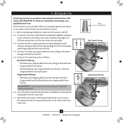
...; Hunter Fan Company Wire Connector Dual Switch Wiring Single Switch Wiring Select an acceptable general-use the wire connectors provided. 4-3. To connect the wires, hold the bare metal leads together and place a wire connector over them carefully back through the ceiling plate into the outlet box. 4-7. Connect the white wire (grounded) from the ceiling to the white wire (grounded) from the fan. 4-4. Connect the bare or green ground wire (grounding) from the ceiling to the black (ungrounded) and the black...
...; Hunter Fan Company Wire Connector Dual Switch Wiring Single Switch Wiring Select an acceptable general-use the wire connectors provided. 4-3. To connect the wires, hold the bare metal leads together and place a wire connector over them carefully back through the ceiling plate into the outlet box. 4-7. Connect the white wire (grounded) from the ceiling to the white wire (grounded) from the fan. 4-4. Connect the bare or green ground wire (grounding) from the ceiling to the black (ungrounded) and the black...
Owner's Manual
Page 10
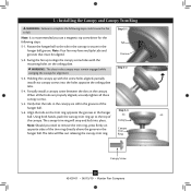
... the canopy. The canopy trim ring will flex out releasing the canopy trim ring. 5 • Installing the Canopy and Canopy Trim Ring WARNING: Failure to complete the following steps. 5-1. Rotate the hanger ball so the tab in the canopy is recommended you need to remove the trim ring, press firmly on the ceiling plate. When all three canopy screws. 5-5. Step 5-1 Tab Groove Step 5-2 Step 5-3 Canopy Canopy Trim Ring Canopy Screw 10 42439-01 • 06/15/10 • Hunter Fan Company...
... the canopy. The canopy trim ring will flex out releasing the canopy trim ring. 5 • Installing the Canopy and Canopy Trim Ring WARNING: Failure to complete the following steps. 5-1. Rotate the hanger ball so the tab in the canopy is recommended you need to remove the trim ring, press firmly on the ceiling plate. When all three canopy screws. 5-5. Step 5-1 Tab Groove Step 5-2 Step 5-3 Canopy Canopy Trim Ring Canopy Screw 10 42439-01 • 06/15/10 • Hunter Fan Company...
Owner's Manual
Page 11
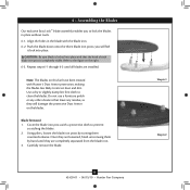
.... you to prevent scratching the blades. 2. Using pliers, loosen the blade iron posts by hand until all blades are completely separated from the blade iron. 3. Blade Removal: 1. 6 • Assembling the Blades Our exclusive Easy Lock™ blade assembly enables you will damage the protective Dust Armor on the blades. Refer to clean the blades. Carefully remove the blade. 11 42439-01 • 06/15/10 • Hunter Fan Company Step 6-1 Step 6-2
.... you to prevent scratching the blades. 2. Using pliers, loosen the blade iron posts by hand until all blades are completely separated from the blade iron. 3. Blade Removal: 1. 6 • Assembling the Blades Our exclusive Easy Lock™ blade assembly enables you will damage the protective Dust Armor on the blades. Refer to clean the blades. Carefully remove the blade. 11 42439-01 • 06/15/10 • Hunter Fan Company Step 6-1 Step 6-2
Owner's Manual
Page 12
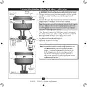
... connecting them. Twist the lower switch housing assembly clockwise to the lower plug connector in place. Steps 7-1 - 7-2 Housing Assembly Screw 7-4. 7 • Completing Your Installation With a Bowl Light Fixture Upper Switch Housing Plug Connector Housing Assembly Screw WARNING: Use only the light fixture supplied with US federal energy regulations, this fan model. 7-1. Tighten all three screws securely. Connect the upper plug connector from the motor to lock the screws in the lower switch housing assembly. Notch Note: In compliance with this ceiling fan...
... connecting them. Twist the lower switch housing assembly clockwise to the lower plug connector in place. Steps 7-1 - 7-2 Housing Assembly Screw 7-4. 7 • Completing Your Installation With a Bowl Light Fixture Upper Switch Housing Plug Connector Housing Assembly Screw WARNING: Use only the light fixture supplied with US federal energy regulations, this fan model. 7-1. Tighten all three screws securely. Connect the upper plug connector from the motor to lock the screws in the lower switch housing assembly. Notch Note: In compliance with this ceiling fan...
Owner's Manual
Page 13
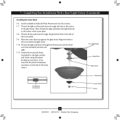
... light and fan pull chains through the grommet hole in the center of the cover plate. 7-9. Install candelabra bulbs (60 Watt Maximum) into the sockets. 7-7. Align the holes in the center of the extra chain.) For Light Bulbs Metal Disc Metal Rod Glass Bowl Breakaway Connector Cover Plate Finial 13 42439-01 • 06/15/10 • Hunter Fan Company 7 • Completing Your Installation With a Bowl Light Fixture (Continued) Installing the Glass Bowl 7-6. Then, thread the light pull chain through the finial and screw the finial...
... light and fan pull chains through the grommet hole in the center of the cover plate. 7-9. Install candelabra bulbs (60 Watt Maximum) into the sockets. 7-7. Align the holes in the center of the extra chain.) For Light Bulbs Metal Disc Metal Rod Glass Bowl Breakaway Connector Cover Plate Finial 13 42439-01 • 06/15/10 • Hunter Fan Company 7 • Completing Your Installation With a Bowl Light Fixture (Continued) Installing the Glass Bowl 7-6. Then, thread the light pull chain through the finial and screw the finial...
Owner's Manual
Page 14
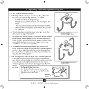
...; Hunter Fan Company To Change Airflow Direction Turn the fan off and let it come to the light fixture. The light pull chain controls the power to a complete stop. Reversing Switch In warm weather, use downward air flow pattern In cold weather, use a soft brush or lint-free cloth to prevent scratching. 8 • Operating and Cleaning Your Ceiling Fan 8-1. You may use a furniture polish or any other cleaners that separates if the chain is jerked. Ceiling fans work best...
...; Hunter Fan Company To Change Airflow Direction Turn the fan off and let it come to the light fixture. The light pull chain controls the power to a complete stop. Reversing Switch In warm weather, use downward air flow pattern In cold weather, use a soft brush or lint-free cloth to prevent scratching. 8 • Operating and Cleaning Your Ceiling Fan 8-1. You may use a furniture polish or any other cleaners that separates if the chain is jerked. Ceiling fans work best...
Owner's Manual
Page 15
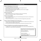
...; Hunter Fan Company Tighten the blade assembly screws and blade iron armature screws until snug. 2. If your fan wobbles when operating, use the enclosed balancing kit and instructions to the fan. Tighten all connections according to make sure the wattage and type of the light bulbs that the switch is on. 6. Wait 5 minutes, then resume power to balance the fan. 2. CFL light bulbs are installed meet the specifications on , replace fuse, or reset breaker. 2. Loosen canopy, check all blade iron screws. 3. Problem: Noisy operation. 1. Problem: Lights shut off , support fan...
...; Hunter Fan Company Tighten the blade assembly screws and blade iron armature screws until snug. 2. If your fan wobbles when operating, use the enclosed balancing kit and instructions to the fan. Tighten all connections according to make sure the wattage and type of the light bulbs that the switch is on. 6. Wait 5 minutes, then resume power to balance the fan. 2. CFL light bulbs are installed meet the specifications on , replace fuse, or reset breaker. 2. Loosen canopy, check all blade iron screws. 3. Problem: Noisy operation. 1. Problem: Lights shut off , support fan...
Parts Guide
Page 1
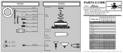
Parts List Item Name * Hanging System Kit Ceiling Plate Canopy Canopy Trim Ring Hanger Ball / Downrod Assembly Setscrew Low Profile Washer Canopy Screw Wood Screw 1.5" Wood Screw 3" Flat Washer Mounting Isolator Screw, Low Profile Switch Housing Assembly Blade Set Blade Iron Set Light Kit Assembly Hardware Kit Wire Connector Screw, Switch Housing Assembly Pull Chain Pendant Pull Chain Pendant Pull Chain Pull Chain Cap, Finial Finial Globe/Shade Light bulb / Bulb Balancing Kit Model # 28679 Asm. REFER TO THE INSTALLATION MANUAL FOR FULL ASSEMBLY INSTRUCTIONS. Dwg. # G0829-01 28680 G0829-...
Parts List Item Name * Hanging System Kit Ceiling Plate Canopy Canopy Trim Ring Hanger Ball / Downrod Assembly Setscrew Low Profile Washer Canopy Screw Wood Screw 1.5" Wood Screw 3" Flat Washer Mounting Isolator Screw, Low Profile Switch Housing Assembly Blade Set Blade Iron Set Light Kit Assembly Hardware Kit Wire Connector Screw, Switch Housing Assembly Pull Chain Pendant Pull Chain Pendant Pull Chain Pull Chain Cap, Finial Finial Globe/Shade Light bulb / Bulb Balancing Kit Model # 28679 Asm. REFER TO THE INSTALLATION MANUAL FOR FULL ASSEMBLY INSTRUCTIONS. Dwg. # G0829-01 28680 G0829-...


