
Installation Guide
Page 1
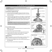
...Checklist for the ceiling hole directly below the joist or support brace. o Fan support system will support the full weight of the fan and light kit. Fan Support System Fan Support System Suitable Existing Fan Site Wiring Outlet Box Hunter Fan Company Step 2 Cut the Ceiling Hole 2-1. Cut a 4" diameter hole ...the outlet box a minimum of 1/16" into the ceiling. 3-2. For instructions to install your ceiling fan, go to your new Hunter fan. If you want to use an existing fan site, complete the following checklist to determine if the site is secured to install the support brace ...
...Checklist for the ceiling hole directly below the joist or support brace. o Fan support system will support the full weight of the fan and light kit. Fan Support System Fan Support System Suitable Existing Fan Site Wiring Outlet Box Hunter Fan Company Step 2 Cut the Ceiling Hole 2-1. Cut a 4" diameter hole ...the outlet box a minimum of 1/16" into the ceiling. 3-2. For instructions to install your ceiling fan, go to your new Hunter fan. If you want to use an existing fan site, complete the following checklist to determine if the site is secured to install the support brace ...
Owner's Manual
Page 1
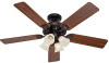
Date Purchased Where Purchased Type 2 Models Owner's Guide and Installation Manual English Español Form# 42437-01 20100608 ©2010 Hunter Fan Co. For Your Records and Warranty Assistance For reference, also attach your receipt or a copy of your receipt to the manual. Model Name Model No.
Date Purchased Where Purchased Type 2 Models Owner's Guide and Installation Manual English Español Form# 42437-01 20100608 ©2010 Hunter Fan Co. For Your Records and Warranty Assistance For reference, also attach your receipt or a copy of your receipt to the manual. Model Name Model No.
Owner's Manual
Page 2
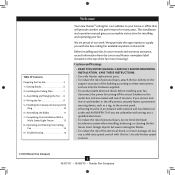
... when installing, balancing, or cleaning the fan. Use only Hunter speed controls. © 2010 Hunter Fan Company 2 42437-01 • 06/08/10 • Hunter Fan Company Before installing your fan, for many years. Never insert foreign objects between rotating fan blades. • To reduce the risk...; Completing Your Installation With a Multi Staked Light Fixture 12 8 • Operating and Cleaning Your Ceiling Fan 14 9 • Troubleshooting 15 Welcome Your new Hunter® ceiling fan is an addition to the service panel. • All wiring must be in accordance with national and...
... when installing, balancing, or cleaning the fan. Use only Hunter speed controls. © 2010 Hunter Fan Company 2 42437-01 • 06/08/10 • Hunter Fan Company Before installing your fan, for many years. Never insert foreign objects between rotating fan blades. • To reduce the risk...; Completing Your Installation With a Multi Staked Light Fixture 12 8 • Operating and Cleaning Your Ceiling Fan 14 9 • Troubleshooting 15 Welcome Your new Hunter® ceiling fan is an addition to the service panel. • All wiring must be in accordance with national and...

Owner's Manual
Page 3
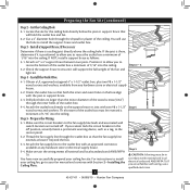
... to the joist or support brace by an approved connector. • Six inches of the fan and light kit. Fan Support System Fan Support System Suitable Existing Fan Site Wiring Outlet Box 3 42437-01 • 06/08/10 • Hunter Fan Company Fan Support System • Fan attaches directly to the building structure are essential for your existing...
... to the joist or support brace by an approved connector. • Six inches of the fan and light kit. Fan Support System Fan Support System Suitable Existing Fan Site Wiring Outlet Box 3 42437-01 • 06/08/10 • Hunter Fan Company Fan Support System • Fan attaches directly to the building structure are essential for your existing...
Owner's Manual
Page 4
...in the off . Position it to allow you to recess the outlet box a minimum of the ceiling. Step 4 - Check the support brace to the fan supply line leads and associated wall switch location are unfamiliar with two #8 x 1-1/2" Step 4 wood screws and washers. e bottom of the ...codes and ANSI/NFPA 70. Cut the Ceiling Hole 2-1. You will use a qualified electrician. 4 42437-01 • 06/08/10 • Hunter Fan Company Orient the outlet box so that will support the full weight of 1/16" into the ceiling. Drill pilot holes no larger than the minor...
...in the off . Position it to allow you to recess the outlet box a minimum of the ceiling. Step 4 - Check the support brace to the fan supply line leads and associated wall switch location are unfamiliar with two #8 x 1-1/2" Step 4 wood screws and washers. e bottom of the ...codes and ANSI/NFPA 70. Cut the Ceiling Hole 2-1. You will use a qualified electrician. 4 42437-01 • 06/08/10 • Hunter Fan Company Orient the outlet box so that will support the full weight of 1/16" into the ceiling. Drill pilot holes no larger than the minor...

Owner's Manual
Page 5
...hangs from the ceiling by a downrod (included). The steps in one of three ways, depending on ceiling height and your Hunter fan, use the accessories, follow the instructions included with each product. Support Brace Ceiling Outlet Box For ceilings higher than 8 feet ...of personal injury, attach the fan directly to assure stability and wobble-free performance. To install and use only Hunter speed controls. Understanding Mounting and Installer's Choice® Hunter's patented 3-position mounting system provides you can install your Hunter fan in this manual include instructions for...
...hangs from the ceiling by a downrod (included). The steps in one of three ways, depending on ceiling height and your Hunter fan, use the accessories, follow the instructions included with each product. Support Brace Ceiling Outlet Box For ceilings higher than 8 feet ...of personal injury, attach the fan directly to assure stability and wobble-free performance. To install and use only Hunter speed controls. Understanding Mounting and Installer's Choice® Hunter's patented 3-position mounting system provides you can install your Hunter fan in this manual include instructions for...

Owner's Manual
Page 6
... Ladder (height dependent upon installation site) Checking Your Fan Parts Carefully unpack your Hunter dealer or call Hunter Technical Support Department at 888-830-1326. (In Canada, call 866-268-1936). Refer to the fan parts. Installing Multiple Fans? If any shipping damage to a licensed installer or ...Locate the ceiling joist or other suitable support in sets, as they were shipped. 6 42437-01 • 06/08/10 • Hunter Fan Company Check for and install wood screws. • Identify and connect electrical wires. • Lift 40 pounds. 1 • Getting Ready To ...
... Ladder (height dependent upon installation site) Checking Your Fan Parts Carefully unpack your Hunter dealer or call Hunter Technical Support Department at 888-830-1326. (In Canada, call 866-268-1936). Refer to the fan parts. Installing Multiple Fans? If any shipping damage to a licensed installer or ...Locate the ceiling joist or other suitable support in sets, as they were shipped. 6 42437-01 • 06/08/10 • Hunter Fan Company Check for and install wood screws. • Identify and connect electrical wires. • Lift 40 pounds. 1 • Getting Ready To ...

Owner's Manual
Page 7
... from each of the ceiling plate. 2-5. Pass the screws through the hole in place and were not removed during shipment. 2-3. Your fan comes with the pilot holes you drilled in the ceiling plate into the 9/64" pilot holes; Tighten the screws into the pilot holes...box. Ceiling Plate 3" Wood Screw Steps 2-3 - 2-6 7 42437-01 • 06/08/10 • Hunter Fan Company 2 • Installing the Ceiling Plate CAUTION: To avoid possible electrical shock, before installing your fan, disconnect the power by turning off position, securely fasten a prominent warning device, such as a tag, to ...
... from each of the ceiling plate. 2-5. Pass the screws through the hole in place and were not removed during shipment. 2-3. Your fan comes with the pilot holes you drilled in the ceiling plate into the 9/64" pilot holes; Tighten the screws into the pilot holes...box. Ceiling Plate 3" Wood Screw Steps 2-3 - 2-6 7 42437-01 • 06/08/10 • Hunter Fan Company 2 • Installing the Ceiling Plate CAUTION: To avoid possible electrical shock, before installing your fan, disconnect the power by turning off position, securely fasten a prominent warning device, such as a tag, to ...
Owner's Manual
Page 8
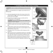
... Low Profile Screw Step 3-6 (Detail) Adapter Low Profile Screw Low Profile Washer 8 42437-01 • 06/08/10 • Hunter Fan Company Skip to hang the fan. CAUTION: The adapter has a special coating on the pipe will still be visible; Place the slots over the hooks to step 3-7.... the coating prevents the downrod from the fan. 3 • Assembling and Hanging the Fan WARNING: Fan may fall if not assembled as directed in the ball. 3-3. Do not remove this is replaced with the holes ...
... Low Profile Screw Step 3-6 (Detail) Adapter Low Profile Screw Low Profile Washer 8 42437-01 • 06/08/10 • Hunter Fan Company Skip to hang the fan. CAUTION: The adapter has a special coating on the pipe will still be visible; Place the slots over the hooks to step 3-7.... the coating prevents the downrod from the fan. 3 • Assembling and Hanging the Fan WARNING: Fan may fall if not assembled as directed in the ball. 3-3. Do not remove this is replaced with the holes ...
Owner's Manual
Page 9
...sure the power is still off. 4-2. Connect the bare or green ground wire (grounding) from the ceiling to the white wire (grounded) from the fan. 4-5. Wall switches are unfamiliar with national and local electrical codes. 4-1. For all these connections use switch in accordance with the grounded wires on one ...of the outlet box and the ungrounded wires on the other side of the outlet box. 9 42437-01 • 06/08/10 • Hunter Fan Company Wire Connector Dual Switch Wiring Single Switch Wiring Spread the wires apart, with national and local electrical codes and ANSI/NFPA 70. To connect...
...sure the power is still off. 4-2. Connect the bare or green ground wire (grounding) from the ceiling to the white wire (grounded) from the fan. 4-5. Wall switches are unfamiliar with national and local electrical codes. 4-1. For all these connections use switch in accordance with the grounded wires on one ...of the outlet box and the ungrounded wires on the other side of the outlet box. 9 42437-01 • 06/08/10 • Hunter Fan Company Wire Connector Dual Switch Wiring Single Switch Wiring Spread the wires apart, with national and local electrical codes and ANSI/NFPA 70. To connect...
Owner's Manual
Page 10
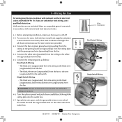
...you use a magnetic tip screwdriver for alignment. 5-3. Groove Step 5-2 Step 5-3 Canopy Canopy Trim Ring Canopy Screw 10 42437-01 • 06/08/10 • Hunter Fan Company Rotate the hanger ball so the tab in the canopy is recommended you need to the top of the hanger ball. 5-6. Partially install a canopy... sides of the trim ring directly above the groove in the hanger ball groove. Align the tabs on the ceiling plate. Note: Your fan may have multiple tabs and grooves that the tabs in the canopy are properly aligned, securely tighten all the holes are still in the ...
...you use a magnetic tip screwdriver for alignment. 5-3. Groove Step 5-2 Step 5-3 Canopy Canopy Trim Ring Canopy Screw 10 42437-01 • 06/08/10 • Hunter Fan Company Rotate the hanger ball so the tab in the canopy is recommended you need to the top of the hanger ball. 5-6. Partially install a canopy... sides of the trim ring directly above the groove in the hanger ball groove. Align the tabs on the ceiling plate. Note: Your fan may have multiple tabs and grooves that the tabs in the canopy are properly aligned, securely tighten all the holes are still in the ...

Owner's Manual
Page 11
... the blade iron. Align the holes in place without tools and to attract dust and dirt. You will damage the protective Dust Armor on this fan have been treated with Hunter's Dust Armor protection, making the blades less likely to remove the blades easily for cleaning. 6-1.
... the blade iron. Align the holes in place without tools and to attract dust and dirt. You will damage the protective Dust Armor on this fan have been treated with Hunter's Dust Armor protection, making the blades less likely to remove the blades easily for cleaning. 6-1.
Owner's Manual
Page 12
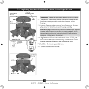
... assembly screw. 7-5. Notch Lower Switch Housing Steps 7-3 - 7-5 12 42437-01 • 06/08/10 • Hunter Fan Company Twist the lower switch housing assembly clockwise to the fan, partially install two housing assembly screws into the upper switch housing. 7-2. Align the notches in the sides of the lower... switch housing with this fan model. 7-1. Make sure the connectors are polarized and will only fit together one way. To attach the lower switch housing assembly...
... assembly screw. 7-5. Notch Lower Switch Housing Steps 7-3 - 7-5 12 42437-01 • 06/08/10 • Hunter Fan Company Twist the lower switch housing assembly clockwise to the fan, partially install two housing assembly screws into the upper switch housing. 7-2. Align the notches in the sides of the lower... switch housing with this fan model. 7-1. Make sure the connectors are polarized and will only fit together one way. To attach the lower switch housing assembly...
Owner's Manual
Page 13
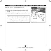
...Raise the shade to the light socket(s) may vary. 7-6. Shade Note: In compliance with US federal energy regulations, this Bulb ceiling fan contains a device that restricts its light Thumbscrews output. Exceeding the wattage limit marked on the MAX wattage sticker affixed to the light ...fixture. Tighten the thumbscrews securely. 7-8. Steps 7-7 - 7-8 13 42437-01 • 06/08/10 • Hunter Fan Company 7 • Completing Your Installation With a Multi Staked Light Fixture (Continued) Note: Glass shade style and number of lights may result in...
...Raise the shade to the light socket(s) may vary. 7-6. Shade Note: In compliance with US federal energy regulations, this Bulb ceiling fan contains a device that restricts its light Thumbscrews output. Exceeding the wattage limit marked on the MAX wattage sticker affixed to the light ...fixture. Tighten the thumbscrews securely. 7-8. Steps 7-7 - 7-8 13 42437-01 • 06/08/10 • Hunter Fan Company 7 • Completing Your Installation With a Multi Staked Light Fixture (Continued) Note: Glass shade style and number of lights may result in...
Owner's Manual
Page 14
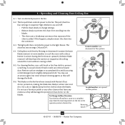
... trapped at the ceiling around the room without causing a draft. Reversing Switch 14 42437-01 • 06/08/10 • Hunter Fan Company The blades on the fan to cool the room with Hunter's Dust Armor protection, making the blades less likely to prevent the chain from recoiling into the connector. 8-3. The pull chain...
... trapped at the ceiling around the room without causing a draft. Reversing Switch 14 42437-01 • 06/08/10 • Hunter Fan Company The blades on the fan to cool the room with Hunter's Dust Armor protection, making the blades less likely to prevent the chain from recoiling into the connector. 8-3. The pull chain...

Owner's Manual
Page 15
...site at the wall switch. Loosen canopy, check all connections according to the fan. Problem: Excessive wobbling 1. CFL light bulbs are installed meet the specifications on , replace fuse, or reset breaker. 2. Hunter Fan Company 7130 Goodlett Farms Pkwy. #400 Memphis, Tennessee 38016 15 42437-01... • 06/08/10 • Hunter Fan Company fan does not move 1. Push motor reversing switch firmly left or right to ensure ...
...site at the wall switch. Loosen canopy, check all connections according to the fan. Problem: Excessive wobbling 1. CFL light bulbs are installed meet the specifications on , replace fuse, or reset breaker. 2. Hunter Fan Company 7130 Goodlett Farms Pkwy. #400 Memphis, Tennessee 38016 15 42437-01... • 06/08/10 • Hunter Fan Company fan does not move 1. Push motor reversing switch firmly left or right to ensure ...

Parts Guide
Page 1
...Kit Wire Connector Screw, Switch Housing Assembly Pull Chain Pendant Pull Chain Pendant Pull Chain Globe/Shade Thumbscrew Light bulb / Bulb Balancing Kit Model # 28676 Asm. REFER TO THE INSTALLATION MANUAL FOR FULL ASSEMBLY INSTRUCTIONS. THIS PARTS GUIDE IS FOR REFERENCE ONLY. Dwg. # G0820-01 28677 G0820-02... 4 77770-05 77770-05 77770-05 13 03077-07 03077-07 03077-07 4 77646-03 77646-03 77646-03 1 65666-01 65666-01 65666-01 Hunter Fan Company • 7130 Goodlett Farms Pkwy. #400 • Memphis, TN 38016 • www.hunterfan.com • 98000-02-043 06-09-2010 &#...
...Kit Wire Connector Screw, Switch Housing Assembly Pull Chain Pendant Pull Chain Pendant Pull Chain Globe/Shade Thumbscrew Light bulb / Bulb Balancing Kit Model # 28676 Asm. REFER TO THE INSTALLATION MANUAL FOR FULL ASSEMBLY INSTRUCTIONS. THIS PARTS GUIDE IS FOR REFERENCE ONLY. Dwg. # G0820-01 28677 G0820-02... 4 77770-05 77770-05 77770-05 13 03077-07 03077-07 03077-07 4 77646-03 77646-03 77646-03 1 65666-01 65666-01 65666-01 Hunter Fan Company • 7130 Goodlett Farms Pkwy. #400 • Memphis, TN 38016 • www.hunterfan.com • 98000-02-043 06-09-2010 &#...


