
Installation Guide
Page 1
... Existing Fan Site Wiring Outlet Box Hunter Fan Company Step 2 Cut the Ceiling Hole 2-1. Locate the site for safety, reliable operation, maximum efficiency, and energy savings. Steps 2 - 3 Step 3 Install a Support Brace, If Necessary Determine if there is positioned to allow you cannot check off every item, prepare a new fan site as follows: 3-1. If the joist is there, determine if it is a ceiling joist directly above the floor...
... Existing Fan Site Wiring Outlet Box Hunter Fan Company Step 2 Cut the Ceiling Hole 2-1. Locate the site for safety, reliable operation, maximum efficiency, and energy savings. Steps 2 - 3 Step 3 Install a Support Brace, If Necessary Determine if there is positioned to allow you cannot check off every item, prepare a new fan site as follows: 3-1. If the joist is there, determine if it is a ceiling joist directly above the floor...

Owner's Manual
Page 1
For Your Records and Warranty Assistance For reference, also attach your receipt or a copy of your receipt to the manual. Date Purchased Where Purchased Type 2 Models Owner's Guide and Installation Manual English Español Form# 42419-01 20081124 ©2008 Hunter Fan Co. Model Name Model No.
For Your Records and Warranty Assistance For reference, also attach your receipt or a copy of your receipt to the manual. Date Purchased Where Purchased Type 2 Models Owner's Guide and Installation Manual English Español Form# 42419-01 20081124 ©2008 Hunter Fan Co. Model Name Model No.

Owner's Manual
Page 2
...; Hanging and Wiring the Fan 7 5 • Installing the Canopy and Canopy Trim Ring 8 6 • Assembling the Blades 9 7 • Setting the Remote Transmitter _ and Receiver 10 8 • Completing Your Installation 11 9 • Operating the Remote Control _ and Mounting the Holder 14 10 • Operating and Cleaning Your _ Ceiling Fan 15 11 • Troubleshooting 16 Welcome Your new Hunter® ceiling fan is an addition to your home or office that will provide comfort and performance for installing and operating your fan, disconnect the power...
...; Hanging and Wiring the Fan 7 5 • Installing the Canopy and Canopy Trim Ring 8 6 • Assembling the Blades 9 7 • Setting the Remote Transmitter _ and Receiver 10 8 • Completing Your Installation 11 9 • Operating the Remote Control _ and Mounting the Holder 14 10 • Operating and Cleaning Your _ Ceiling Fan 15 11 • Troubleshooting 16 Welcome Your new Hunter® ceiling fan is an addition to your home or office that will provide comfort and performance for installing and operating your fan, disconnect the power...
Owner's Manual
Page 3
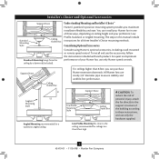
Considering Optional Accessories Consider using Hunter's optional accessories, including a wall-mounted or remote speed control. You can purchase Hunter extension downrods. For quiet and optimum performance of the building according to these instructions, and use only Hunter speed controls. Support Brace Ceiling Outlet Box For ceilings higher than 8 feet high CAUTION: To reduce the risk of personal injury, attach the fan directly to the support structure of your preference: Low Profile, Standard, or Angled mounting. Angled Mounting Style 8 12 Angled Mounting recommended...
Considering Optional Accessories Consider using Hunter's optional accessories, including a wall-mounted or remote speed control. You can purchase Hunter extension downrods. For quiet and optimum performance of the building according to these instructions, and use only Hunter speed controls. Support Brace Ceiling Outlet Box For ceilings higher than 8 feet high CAUTION: To reduce the risk of personal injury, attach the fan directly to the support structure of your preference: Low Profile, Standard, or Angled mounting. Angled Mounting Style 8 12 Angled Mounting recommended...
Owner's Manual
Page 4
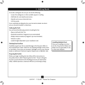
... screws. • Identify and connect electrical wires. • Lift 40 pounds. If any shipping damage to the included Parts Guide. Installing Multiple Fans? Preparing the Fan Site Before you are installing more than one fan, keep the fan blades and blade irons (if applicable) in ceiling. • Drill holes for safety, reliable operation, maximum efficiency, and energy savings. Gathering the Tools You will need help installing the fan, your Hunter dealer or call Hunter Technical Support...
... screws. • Identify and connect electrical wires. • Lift 40 pounds. If any shipping damage to the included Parts Guide. Installing Multiple Fans? Preparing the Fan Site Before you are installing more than one fan, keep the fan blades and blade irons (if applicable) in ceiling. • Drill holes for safety, reliable operation, maximum efficiency, and energy savings. Gathering the Tools You will need help installing the fan, your Hunter dealer or call Hunter Technical Support...

Owner's Manual
Page 5
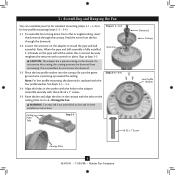
... box down through the hole in the wood support structure. Note: The isolators should be flush against the ceiling. 2-5. Step 2-2 Flat Washer Toward Ceiling Peak Steps 2-3 - 2-5 3" Screw For Angled Ceilings: Be sure to orient the ceiling plate so that the two tabs are pointing toward the ceiling peak. 5 42419-01 • 11/24/08 • Hunter Fan Company 2 • Installing the Ceiling Plate 2-1. Thread the lead wires from each isolator...
... box down through the hole in the wood support structure. Note: The isolators should be flush against the ceiling. 2-5. Step 2-2 Flat Washer Toward Ceiling Peak Steps 2-3 - 2-5 3" Screw For Angled Ceilings: Be sure to orient the ceiling plate so that the two tabs are pointing toward the ceiling peak. 5 42419-01 • 11/24/08 • Hunter Fan Company 2 • Installing the Ceiling Plate 2-1. Thread the lead wires from each isolator...
Owner's Manual
Page 6
... on the adapter to 4 • Wiring the Fan. Once assembled, do not remove the downrod. 3-3. See Steps 3-3 - 3-4. 3-4. To assemble fan to Step 3-5. Place the low profile washer into the canopy. Be sure the green ground wire is replaced with the low profile washer. Align the holes in the adapter. WARNING: Fan may fall if not assembled as directed in the canopy with three #8-32 x 1" screws. 3-5. Do not remove this is fully installed, 2-3 threads on the ceiling plate. Securely...
... on the adapter to 4 • Wiring the Fan. Once assembled, do not remove the downrod. 3-3. See Steps 3-3 - 3-4. 3-4. To assemble fan to Step 3-5. Place the low profile washer into the canopy. Be sure the green ground wire is replaced with the low profile washer. Align the holes in the adapter. WARNING: Fan may fall if not assembled as directed in the canopy with three #8-32 x 1" screws. 3-5. Do not remove this is fully installed, 2-3 threads on the ceiling plate. Securely...
Owner's Manual
Page 7
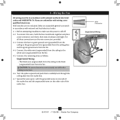
... wires apart, with national and local electrical codes. 4-1. Select an acceptable general-use switch in accordance with wiring, use a qualified electrician. Connect the white wire (ungrounded) from the ceiling to the green ground wire (grounded) from the ceiling plate and the green ground wire from the fan. 4-4. fsdfsdf Wire Connector Single Switch Wiring 7 42419-01 • 11/24/08 • Hunter Fan Company For all these connections use the wire connectors provided. 4-3. Wall switches are visible after making connections...
... wires apart, with national and local electrical codes. 4-1. Select an acceptable general-use switch in accordance with wiring, use a qualified electrician. Connect the white wire (ungrounded) from the ceiling to the green ground wire (grounded) from the ceiling plate and the green ground wire from the fan. 4-4. fsdfsdf Wire Connector Single Switch Wiring 7 42419-01 • 11/24/08 • Hunter Fan Company For all these connections use the wire connectors provided. 4-3. Wall switches are visible after making connections...
Owner's Manual
Page 8
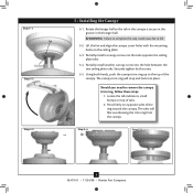
...: 1. The canopy trim ring will flex out releasing the trim ring from the canopy. Locate the tab indicators, small bumps on top of the ring toward the canopy. The tabs will snap and lock into the hole between the two ceiling plate tabs. Rotate the hanger ball so the tab in the canopy is secure in the groove in the hanger ball. Partially install another canopy screw into...
...: 1. The canopy trim ring will flex out releasing the trim ring from the canopy. Locate the tab indicators, small bumps on top of the ring toward the canopy. The tabs will snap and lock into the hole between the two ceiling plate tabs. Rotate the hanger ball so the tab in the canopy is secure in the groove in the hanger ball. Partially install another canopy screw into...
Owner's Manual
Page 9
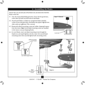
... the blade iron, and attach lightly to a blade iron using three blade assembly screws. For each blade to the fan. Insert the second blade mounting screw, then securely tighten both mounting screws. Remove the blade mounting screws and rubber shipping bumpers from the motor. If you used grommets, the blades may include blade grommets. Note: Some blade mounting screws are tightened. Step 6-1 (Detail) Grommet Use with grommet Blade Assembly Screws Steps 6-1 - 6-2 Use without grommet Blade Mounting Screw Step 6-4 9 42419-01 • 11/24/08 • Hunter Fan Company...
... the blade iron, and attach lightly to a blade iron using three blade assembly screws. For each blade to the fan. Insert the second blade mounting screw, then securely tighten both mounting screws. Remove the blade mounting screws and rubber shipping bumpers from the motor. If you used grommets, the blades may include blade grommets. Note: Some blade mounting screws are tightened. Step 6-1 (Detail) Grommet Use with grommet Blade Assembly Screws Steps 6-1 - 6-2 Use without grommet Blade Mounting Screw Step 6-4 9 42419-01 • 11/24/08 • Hunter Fan Company...
Owner's Manual
Page 10
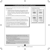
... jumper in the remote transmitter and receiver so that may not cause harmful interference. 2. Setting Jumpers When two or more fans are very small. This device must now set to operate this product. 10 42419-01 • 11/24/08 • Hunter Fan Company IMPORTANT! Changes or modifications not expressly approved by Hunter Fan Company could void your authority to a different code, so that incorporates an air gap switch...
... jumper in the remote transmitter and receiver so that may not cause harmful interference. 2. Setting Jumpers When two or more fans are very small. This device must now set to operate this product. 10 42419-01 • 11/24/08 • Hunter Fan Company IMPORTANT! Changes or modifications not expressly approved by Hunter Fan Company could void your authority to a different code, so that incorporates an air gap switch...
Owner's Manual
Page 11
... fan model. 8-1. The steps below direct you whether or not you want to properly attach and tighten all three screws firmly. Failure to install the light fixture, you the option of installing the fan with an integrated light fixture assembly and an optional switch housing cap and plug button. WARNING: Use only the light fixture supplied with step 8-6 now. Steps 8-1 - 8-3 Housing Assembly Screw Upper Switch Housing 11 42419-01 • 11/24/08 • Hunter Fan Company...
... fan model. 8-1. The steps below direct you whether or not you want to properly attach and tighten all three screws firmly. Failure to install the light fixture, you the option of installing the fan with an integrated light fixture assembly and an optional switch housing cap and plug button. WARNING: Use only the light fixture supplied with step 8-6 now. Steps 8-1 - 8-3 Housing Assembly Screw Upper Switch Housing 11 42419-01 • 11/24/08 • Hunter Fan Company...
Owner's Manual
Page 12
... side screw holes in the lower switch housing assembly. To install each ). Raise the shade to the product. 8-7. Exceeding that restricts the light kit to the upper switch housing with US federal energy regulations, this ceiling fan contains a device that limit or the marked limit on this product may vary. Shade Bulb Steps 8-8 - 8-10 12 42419-01 • 11/24/08 • Hunter Fan Company Note: Both plug connectors are properly aligned before Plug Connector connecting...
... side screw holes in the lower switch housing assembly. To install each ). Raise the shade to the product. 8-7. Exceeding that restricts the light kit to the upper switch housing with US federal energy regulations, this ceiling fan contains a device that limit or the marked limit on this product may vary. Shade Bulb Steps 8-8 - 8-10 12 42419-01 • 11/24/08 • Hunter Fan Company Note: Both plug connectors are properly aligned before Plug Connector connecting...

Owner's Manual
Page 13
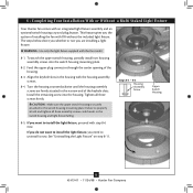
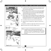
... x 1/2" housing assembly screws. Disconnect the light plug connectors between the two white Light Plug wires. Making sure the mounting holes at the top of the receiver. 8-16. Housing Assembly Screw Steps 8-10 - 8-11 Plug Connector Detail 13 42419-01 • 11/24/08 • Hunter Fan Company Receiver 8-12. Connectors 8-14. Place the receiver into the alternate switch housing. 8 • Completing Your Installation With or Without a Multi Staked Light Fixture (Cont.) Steps 8-6 - 8-9 Light Plug Connector Detail 8-11. Kit 8-15. Align the side screw holes...
... x 1/2" housing assembly screws. Disconnect the light plug connectors between the two white Light Plug wires. Making sure the mounting holes at the top of the receiver. 8-16. Housing Assembly Screw Steps 8-10 - 8-11 Plug Connector Detail 13 42419-01 • 11/24/08 • Hunter Fan Company Receiver 8-12. Connectors 8-14. Place the receiver into the alternate switch housing. 8 • Completing Your Installation With or Without a Multi Staked Light Fixture (Cont.) Steps 8-6 - 8-9 Light Plug Connector Detail 8-11. Kit 8-15. Align the side screw holes...

Owner's Manual
Page 14
... fan off. 9-5. Fan Speed High Fan Speed Low Fan Reverse Fan Speed Medium Fan Off Fan Light Steps 10-1 - 10-4 Step 10-5 14 42419-01 • 11/24/08 • Hunter Fan Company Step 10-6 Push the light button again to any toggle switch plate with a 12-volt type 23A, MN-21 battery or equivalent. 9-6. Or, you reach your desired speed. 9-3. The remote transmitter has individual buttons for turning the fan off the light. 9-4. When necessary, replace the battery...
... fan off. 9-5. Fan Speed High Fan Speed Low Fan Reverse Fan Speed Medium Fan Off Fan Light Steps 10-1 - 10-4 Step 10-5 14 42419-01 • 11/24/08 • Hunter Fan Company Step 10-6 Push the light button again to any toggle switch plate with a 12-volt type 23A, MN-21 battery or equivalent. 9-6. Or, you reach your desired speed. 9-3. The remote transmitter has individual buttons for turning the fan off the light. 9-4. When necessary, replace the battery...
Owner's Manual
Page 15
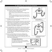
... change settings. • Release slowly to the light fixture. Slide the reversing switch on electrical power to the fan. 10-2.The fan pull chain controls power to the fan. You may use an artistic agent, but never abrasive cleaning agents as the fan finish. Occasionally, apply a light coat of furniture polish for added protection and beauty. Restart fan. Reversing Switch 15 42419-01 • 11/24/08 • Hunter Fan Company 10 • Operating and Cleaning Your Ceiling Fan...
... change settings. • Release slowly to the light fixture. Slide the reversing switch on electrical power to the fan. 10-2.The fan pull chain controls power to the fan. You may use an artistic agent, but never abrasive cleaning agents as the fan finish. Occasionally, apply a light coat of furniture polish for added protection and beauty. Restart fan. Reversing Switch 15 42419-01 • 11/24/08 • Hunter Fan Company 10 • Operating and Cleaning Your Ceiling Fan...
Owner's Manual
Page 16
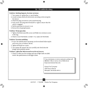
... the hanger ball is on the light socket. Remove the shipping bumpers. If so, replace all blade iron screws. 3. Turn power on 1. If you need parts or service assistance, please call 888‑830‑1326 or visit us at our Web site at http://www.hunterfan.com. Push motor reversing switch firmly left or right to make sure the wattage and type of light bulbs installed match the specifications on . 6. 11 • Troubleshooting Problem...
... the hanger ball is on the light socket. Remove the shipping bumpers. If so, replace all blade iron screws. 3. Turn power on 1. If you need parts or service assistance, please call 888‑830‑1326 or visit us at our Web site at http://www.hunterfan.com. Push motor reversing switch firmly left or right to make sure the wattage and type of light bulbs installed match the specifications on . 6. 11 • Troubleshooting Problem...
Parts Guide
Page 1
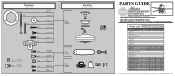
... Parts List Item Name Hanger Bracket Assembly Ceiling Plate Canopy Canopy Trim Ring Hanger Ball / Downrod Assembly Washer, Installers Choice Canopy Screw Locking Screw Wood Screw Flat Washer Mounting Isolator Wood Screw Switch Housing Assembly Blade Iron Set Blade Set Hardware Kit Screw, Switch Housing Assembly Blade Grommet Blade Assembly Screw Screw, Machine, 6-32 Wire Connector Switch Housing, Alternate Switch Housing Cover Switch Housing Plug Button Balancing Kit Remote Control Transmitter Remote Control Cradle Remote Control Receiver Globe/Shade 12 Volt Battery (GP23A) Light bulb / Bulb...
... Parts List Item Name Hanger Bracket Assembly Ceiling Plate Canopy Canopy Trim Ring Hanger Ball / Downrod Assembly Washer, Installers Choice Canopy Screw Locking Screw Wood Screw Flat Washer Mounting Isolator Wood Screw Switch Housing Assembly Blade Iron Set Blade Set Hardware Kit Screw, Switch Housing Assembly Blade Grommet Blade Assembly Screw Screw, Machine, 6-32 Wire Connector Switch Housing, Alternate Switch Housing Cover Switch Housing Plug Button Balancing Kit Remote Control Transmitter Remote Control Cradle Remote Control Receiver Globe/Shade 12 Volt Battery (GP23A) Light bulb / Bulb...


