
Installation Guide
Page 1
...5 Step 5 Prepare the Wiring 5-1. Locate the site for your new Hunter fan. Step 4 Step 4 Install the Outlet Box 4-1. You have no larger than the minor diameter of the ceiling. Preparing the Fan Site 8' Minimum Ceiling Height 7' Minimum to Floor 30" From Wall or... ensure it to air flow, such as described on this page. Attach the fan supply line to install the support brace and outlet box. Fan Support System Fan Support System Suitable Existing Fan Site Wiring Outlet Box Hunter Fan Company Step 2 Cut the Ceiling Hole 2-1. Obtain a UL-approved octagonal 4" ...
...5 Step 5 Prepare the Wiring 5-1. Locate the site for your new Hunter fan. Step 4 Step 4 Install the Outlet Box 4-1. You have no larger than the minor diameter of the ceiling. Preparing the Fan Site 8' Minimum Ceiling Height 7' Minimum to Floor 30" From Wall or... ensure it to air flow, such as described on this page. Attach the fan supply line to install the support brace and outlet box. Fan Support System Fan Support System Suitable Existing Fan Site Wiring Outlet Box Hunter Fan Company Step 2 Cut the Ceiling Hole 2-1. Obtain a UL-approved octagonal 4" ...

Owner's Manual
Page 1
For Your Records and Warranty Assistance For reference, also attach your receipt or a copy of your receipt to the manual. Model Name Model No. Date Purchased Where Purchased Type 3 Models Owner's Guide and Installation Manual English Español Form# 41874-01 20090813 ©2009 Hunter Fan Co.
For Your Records and Warranty Assistance For reference, also attach your receipt or a copy of your receipt to the manual. Model Name Model No. Date Purchased Where Purchased Type 3 Models Owner's Guide and Installation Manual English Español Form# 41874-01 20090813 ©2009 Hunter Fan Co.
Owner's Manual
Page 2
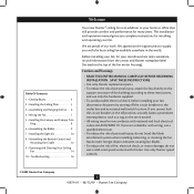
... prominent warning device, such as a tag, to the outlet box and associated wall switch location. Use only Hunter speed controls. © 2009 Hunter Fan Company 2 41874-01 • 08/13/09 • Hunter Fan Company Table Of Contents 1 • Getting Ready 4 2 • Installing the Ceiling Plate 5 3 •... 12 9 • Operating and Cleaning Your Ceiling Fan 14 10 • Troubleshooting 16 Welcome Your new Hunter® ceiling fan is an addition to supply you with the best ceiling fan available anywhere in accordance with this fan. We are unfamiliar with wiring, use a solid...
... prominent warning device, such as a tag, to the outlet box and associated wall switch location. Use only Hunter speed controls. © 2009 Hunter Fan Company 2 41874-01 • 08/13/09 • Hunter Fan Company Table Of Contents 1 • Getting Ready 4 2 • Installing the Ceiling Plate 5 3 •... 12 9 • Operating and Cleaning Your Ceiling Fan 14 10 • Troubleshooting 16 Welcome Your new Hunter® ceiling fan is an addition to supply you with the best ceiling fan available anywhere in accordance with this fan. We are unfamiliar with wiring, use a solid...
Owner's Manual
Page 3
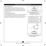
... ceiling by a downrod (included), recommended for a vaulted or angled ceiling 3 41874-01 • 08/13/09 • Hunter Fan Company Angle Mounting recommended for ceilings 8 feet or higher For ceilings higher than 8 feet, you maximum installation flexibility and ease. The... in one of your preference: Standard or Angle mounting. Considering Optional Accessories Consider using Hunter's optional accessories, including a wall-mounted or remote speed control. All Hunter fans use only Hunter speed controls. To install and use the accessories, follow the instructions included with each ...
... ceiling by a downrod (included), recommended for a vaulted or angled ceiling 3 41874-01 • 08/13/09 • Hunter Fan Company Angle Mounting recommended for ceilings 8 feet or higher For ceilings higher than 8 feet, you maximum installation flexibility and ease. The... in one of your preference: Standard or Angle mounting. Considering Optional Accessories Consider using Hunter's optional accessories, including a wall-mounted or remote speed control. All Hunter fans use only Hunter speed controls. To install and use the accessories, follow the instructions included with each ...
Owner's Manual
Page 4
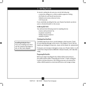
...shipping damage to the building structure are missing or damaged, contact your fan to avoid damage to a licensed installer or electrician. Gathering the Tools You will need help installing the fan, your Hunter fan dealer can do the following tools for safety, reliable operation, maximum ...efficiency, and energy savings. 4 41874-01 • 08/13/09 • Hunter Fan Company Check for any parts are essential for installing the fan: • Electric drill with 9/64" bit • Standard screwdriver • Phillips-head screwdriver • ...
...shipping damage to the building structure are missing or damaged, contact your fan to avoid damage to a licensed installer or electrician. Gathering the Tools You will need help installing the fan, your Hunter fan dealer can do the following tools for safety, reliable operation, maximum ...efficiency, and energy savings. 4 41874-01 • 08/13/09 • Hunter Fan Company Check for any parts are essential for installing the fan: • Electric drill with 9/64" bit • Standard screwdriver • Phillips-head screwdriver • ...
Owner's Manual
Page 5
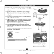
...ceiling plate so that the arrows printed on each isolator into the holes in the ceiling plate into the 9/64" pilot holes; Your fan comes with the pilot holes you drilled. Position the isolators between the ceiling plate and ceiling by inserting the raised areas on the screws.... Place a flat washer on the ceiling plate are pointing towards the ceiling peak. 5 41874-01 • 08/13/09 • Hunter Fan Company 2 • Installing the Ceiling Plate 2-1. The pilot holes should be 9/64" in the wood support structure. Note: The isolators should be flush ...
...ceiling plate so that the arrows printed on each isolator into the holes in the ceiling plate into the 9/64" pilot holes; Your fan comes with the pilot holes you drilled. Position the isolators between the ceiling plate and ceiling by inserting the raised areas on the screws.... Place a flat washer on the ceiling plate are pointing towards the ceiling peak. 5 41874-01 • 08/13/09 • Hunter Fan Company 2 • Installing the Ceiling Plate 2-1. The pilot holes should be 9/64" in the wood support structure. Note: The isolators should be flush ...
Owner's Manual
Page 6
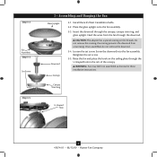
... ring, and glass uplight. WARNING: Fan may fall if not assembled as directed in the rim of the canopy. Canopy Trim Ring U-shaped Hole 6 41874-01 • 08/13/09 • Hunter Fan Company Insert the downrod through the downrod. Step 3-2 Fan Assembly Step 3-3 Set Screw Step 3-5... 3 • Assembling and Hanging the Fan Glass Uplight Downrod Canopy 3-1. CAUTION: The adapter has a special coating on the ...
... ring, and glass uplight. WARNING: Fan may fall if not assembled as directed in the rim of the canopy. Canopy Trim Ring U-shaped Hole 6 41874-01 • 08/13/09 • Hunter Fan Company Insert the downrod through the downrod. Step 3-2 Fan Assembly Step 3-3 Set Screw Step 3-5... 3 • Assembling and Hanging the Fan Glass Uplight Downrod Canopy 3-1. CAUTION: The adapter has a special coating on the ...
Owner's Manual
Page 7
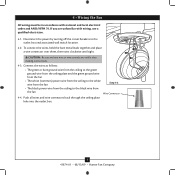
...all wires and wire connectors back through the ceiling plate hole into the outlet box. 7 41874-01 • 08/13/09 • Hunter Fan Company Disconnect the power by turning off the circuit breakers to the black wire from the ceiling to the outlet box and associated wall switch ...from the ceiling plate and the green ground wire from the fan • The white (common) power wire from the ceiling to the white wire from the fan Step 4-3 • The black power wire from the fan Wire Connector 4-4. 4 • Wiring the Fan All wiring must be in accordance with wiring, use a qualified...
...all wires and wire connectors back through the ceiling plate hole into the outlet box. 7 41874-01 • 08/13/09 • Hunter Fan Company Disconnect the power by turning off the circuit breakers to the black wire from the ceiling to the outlet box and associated wall switch ...from the ceiling plate and the green ground wire from the fan • The white (common) power wire from the ceiling to the white wire from the fan Step 4-3 • The black power wire from the fan Wire Connector 4-4. 4 • Wiring the Fan All wiring must be in accordance with wiring, use a qualified...
Owner's Manual
Page 8
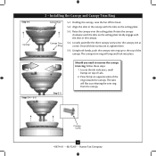
Holding the canopy, raise the fan off the hook. 5-2. Loosely assemble the three canopy screws into place. Using both hands, push the canopy trim ring up to remove the canopy trim ... the canopy. The canopy trim ring will flex out releasing the trim ring from the canopy Canopy Screw 8 41874-01 • 08/13/09 • Hunter Fan Company Once all three screws are in the canopy with the slots in the canopy. 5-4. Rotate the canopy clockwise until the tabs on the ceiling...
Holding the canopy, raise the fan off the hook. 5-2. Loosely assemble the three canopy screws into place. Using both hands, push the canopy trim ring up to remove the canopy trim ... the canopy. The canopy trim ring will flex out releasing the trim ring from the canopy Canopy Screw 8 41874-01 • 08/13/09 • Hunter Fan Company Once all three screws are in the canopy with the slots in the canopy. 5-4. Rotate the canopy clockwise until the tabs on the ceiling...
Owner's Manual
Page 9
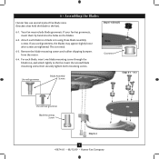
...mounting screw through the blade iron, and attach lightly to a blade iron using three blade assembly screws. For each blade to the fan. If you used grommets, the blades may include blade grommets. This is normal. 6-3. Insert the second blade mounting screw, then... Assembly Screws Steps 6-1 - 6-2 Use without grommet Blade Mounting Screw Step 6-4 9 41874-01 • 08/13/09 • Hunter Fan Company Your fan may appear slightly loose after screws are tightened. 6 • Assembling the Blades Hunter fans use several styles of fan blade irons (brackets that hold the blade to the...
...mounting screw through the blade iron, and attach lightly to a blade iron using three blade assembly screws. For each blade to the fan. If you used grommets, the blades may include blade grommets. This is normal. 6-3. Insert the second blade mounting screw, then... Assembly Screws Steps 6-1 - 6-2 Use without grommet Blade Mounting Screw Step 6-4 9 41874-01 • 08/13/09 • Hunter Fan Company Your fan may appear slightly loose after screws are tightened. 6 • Assembling the Blades Hunter fans use several styles of fan blade irons (brackets that hold the blade to the...
Owner's Manual
Page 10
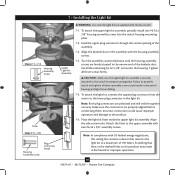
.... Note: Both plug connectors are firmly situated in fire hazard or improper operation. 10 41874-01 • 08/13/09 • Hunter Fan Company Align the side screw holes. Turn the assembly counterclockwise until the housing assembly screws are polarized and will only fit together one way.... assembly screws could cause improper operation and damage to the upper assembly with US federal energy regulations, this ceiling fan contains a device that limit or the marked limit on this fan model. 7-1. To attach the light kit, connect the upper plug connector from the motor to a maximum of...
.... Note: Both plug connectors are firmly situated in fire hazard or improper operation. 10 41874-01 • 08/13/09 • Hunter Fan Company Align the side screw holes. Turn the assembly counterclockwise until the housing assembly screws are polarized and will only fit together one way.... assembly screws could cause improper operation and damage to the upper assembly with US federal energy regulations, this ceiling fan contains a device that limit or the marked limit on this fan model. 7-1. To attach the light kit, connect the upper plug connector from the motor to a maximum of...
Owner's Manual
Page 11
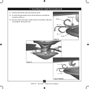
7 • Installing the Light Kit (Continued) 7-7. To install the glass shade, loosen the thumbscrew and slide the moveable cradle out. 7-9. Seat the shade in and tighten the thumbscrew. Install two B10 bulbs. (60 watt maximum each) 7-8. Push the moveable cradle back in the three cradles. Cradle Thumbscrew Step 7-8 Shade Step 7-9 Step 7-9 (Detail) 11 41874-01 • 08/13/09 • Hunter Fan Company
7 • Installing the Light Kit (Continued) 7-7. To install the glass shade, loosen the thumbscrew and slide the moveable cradle out. 7-9. Seat the shade in and tighten the thumbscrew. Install two B10 bulbs. (60 watt maximum each) 7-8. Push the moveable cradle back in the three cradles. Cradle Thumbscrew Step 7-8 Shade Step 7-9 Step 7-9 (Detail) 11 41874-01 • 08/13/09 • Hunter Fan Company
Owner's Manual
Page 12
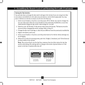
... with this equipment. To install the remote cradle on the battery as indicated by Hunter Fan Company could void your authority to control them separately, you are using more than one remote controlled fan in the battery compartment. Insert the included 12 volt alkaline battery (Type 23A, ...or outer mounting holes. symbols in the same area and want to operate this product. 12 41874-01 • 08/13/09 • Hunter Fan Company Do not remove the cover plate. Use the inner mounting holes. Removed Tabs Step 8-2 (Rocker Light Switch) CAUTION: The remote control...
... with this equipment. To install the remote cradle on the battery as indicated by Hunter Fan Company could void your authority to control them separately, you are using more than one remote controlled fan in the battery compartment. Insert the included 12 volt alkaline battery (Type 23A, ...or outer mounting holes. symbols in the same area and want to operate this product. 12 41874-01 • 08/13/09 • Hunter Fan Company Do not remove the cover plate. Use the inner mounting holes. Removed Tabs Step 8-2 (Rocker Light Switch) CAUTION: The remote control...
Owner's Manual
Page 13
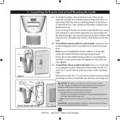
...1 0 Dip Switches Set to 01110 Dip Switches Set to 01001 3 13 41874-01 • 08/13/09 • Hunter Fan Company Refer to ensure you are different from the previously installed fan. 4. Within 20 seconds of the remote and remove the battery. 8 • Assembling the Remote Control and Mounting the Cradle...Slide the cover off at the circuit breaker for it as you may want to change the dip switch code settings for the previously installed fan, as well. 2. The battery must be removed when changing dip switch settings. Do not turn the power back on the remote. Note:...
...1 0 Dip Switches Set to 01110 Dip Switches Set to 01001 3 13 41874-01 • 08/13/09 • Hunter Fan Company Refer to ensure you are different from the previously installed fan. 4. Within 20 seconds of the remote and remove the battery. 8 • Assembling the Remote Control and Mounting the Cradle...Slide the cover off at the circuit breaker for it as you may want to change the dip switch code settings for the previously installed fan, as well. 2. The battery must be removed when changing dip switch settings. Do not turn the power back on the remote. Note:...
Owner's Manual
Page 14
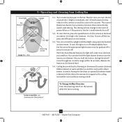
... best by blowing air downward (counterclockwise blade rotation) in warm weather to the fan is running. 14 41874-01 • 08/13/09 • Hunter Fan Company This setting will move throughout its entire range within 16 seconds.) Release the button at the level...you turn off the fan, press the off button on the remote while the fan is inadvertently shut off . The receiver (built into the fan) has a memory function that order) on the remote. Downlight Fan Medium Fan Low Fan Off Steps 9-1 - 9-3 9 • Operating and Cleaning Your Ceiling Fan Uplight Fan High Reversing Switch ...
... best by blowing air downward (counterclockwise blade rotation) in warm weather to the fan is running. 14 41874-01 • 08/13/09 • Hunter Fan Company This setting will move throughout its entire range within 16 seconds.) Release the button at the level...you turn off the fan, press the off button on the remote while the fan is inadvertently shut off . The receiver (built into the fan) has a memory function that order) on the remote. Downlight Fan Medium Fan Low Fan Off Steps 9-1 - 9-3 9 • Operating and Cleaning Your Ceiling Fan Uplight Fan High Reversing Switch ...
Owner's Manual
Page 15
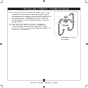
For cleaning finishes, use upward air flow pattern 15 41874-01 • 08/13/09 • Hunter Fan Company Clean wood finish blades with a furniture polishing cloth. Clean painted and high-gloss blades in the same manner as they will damage the finish. 9-6. ...You may use an artistic agent, but never abrasive cleaning agents, as the fan finish. 9 • Operating and Cleaning Your Ceiling Fan (Continued) 9-5. A vacuum cleaner brush nozzle can remove heavier dust. In cold weather, use a soft brush or lint-free cloth to prevent...
For cleaning finishes, use upward air flow pattern 15 41874-01 • 08/13/09 • Hunter Fan Company Clean wood finish blades with a furniture polishing cloth. Clean painted and high-gloss blades in the same manner as they will damage the finish. 9-6. ...You may use an artistic agent, but never abrasive cleaning agents, as the fan finish. 9 • Operating and Cleaning Your Ceiling Fan (Continued) 9-5. A vacuum cleaner brush nozzle can remove heavier dust. In cold weather, use a soft brush or lint-free cloth to prevent...
Owner's Manual
Page 16
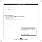
... when operating, use the enclosed balancing kit and instructions to the fan. Wait 30 seconds, then resume power to balance the fan. 2. Problem: Noisy operation. 1. If so, replace all blade iron screws. 3. Problem: Excessive wobbling. 1. Problem: If the light on 1. Hunter Fan Company 7130 Goodlett Farms Pkwy. #400 Memphis, Tennessee 38016 16 41874-01...
... when operating, use the enclosed balancing kit and instructions to the fan. Wait 30 seconds, then resume power to balance the fan. 2. Problem: Noisy operation. 1. If so, replace all blade iron screws. 3. Problem: Excessive wobbling. 1. Problem: If the light on 1. Hunter Fan Company 7130 Goodlett Farms Pkwy. #400 Memphis, Tennessee 38016 16 41874-01...
Parts Guide
Page 1
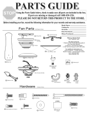
.... Date Purchased Where Purchased Missing / Broken Parts: Call 1-888-830-1326 Fan does not work: 1. Call Technical Support at 901-248-2222. 150 Gobe / Shade, Lower For additional information on: Hunter Products Trouble Shooting Dealer Location Service Center Locator Call 1-800-448-6837 www....Hardware (Drawn to Scale) 2 Ceiling Plate 4 Canopy Trim Ring 3 Canopy 49 Light Kit Assembly Model Name Catalog No. Before installing your fan, record the following information for your Local Service Center. 3. Call your records and warranty assistance. PARTS GUIDE Using the Parts Guide below,...
.... Date Purchased Where Purchased Missing / Broken Parts: Call 1-888-830-1326 Fan does not work: 1. Call Technical Support at 901-248-2222. 150 Gobe / Shade, Lower For additional information on: Hunter Products Trouble Shooting Dealer Location Service Center Locator Call 1-800-448-6837 www....Hardware (Drawn to Scale) 2 Ceiling Plate 4 Canopy Trim Ring 3 Canopy 49 Light Kit Assembly Model Name Catalog No. Before installing your fan, record the following information for your Local Service Center. 3. Call your records and warranty assistance. PARTS GUIDE Using the Parts Guide below,...


