
Installation Guide
Page 1
... connector. Outlet Box o e outlet box is at least 8 feet high. • e fan blades have now successfully prepared your new Hunter fan. o e bottom of 1/16" into the ceiling. 3-2. o Six inches of 1/16" into the ceiling. Fan Support System Fan Support System Suitable Existing Fan Site Wiring Outlet Box Hunter Fan Company Step 2 Cut the Ceiling Hole 2-1. Steps 2 - 3 Step 3 Install a Support Brace, If Necessary Determine if there is directly below the joist or support brace that the fan...
... connector. Outlet Box o e outlet box is at least 8 feet high. • e fan blades have now successfully prepared your new Hunter fan. o e bottom of 1/16" into the ceiling. 3-2. o Six inches of 1/16" into the ceiling. Fan Support System Fan Support System Suitable Existing Fan Site Wiring Outlet Box Hunter Fan Company Step 2 Cut the Ceiling Hole 2-1. Steps 2 - 3 Step 3 Install a Support Brace, If Necessary Determine if there is directly below the joist or support brace that the fan...

Owner's Manual
Page 1
Date Purchased Where Purchased Type 3 Models Owner's Guide and Installation Manual English Español Form# 41874-01 20090813 ©2009 Hunter Fan Co. For Your Records and Warranty Assistance For reference, also attach your receipt or a copy of your receipt to the manual. Model Name Model No.
Date Purchased Where Purchased Type 3 Models Owner's Guide and Installation Manual English Español Form# 41874-01 20090813 ©2009 Hunter Fan Co. For Your Records and Warranty Assistance For reference, also attach your receipt or a copy of your receipt to the manual. Model Name Model No.
Owner's Manual
Page 2
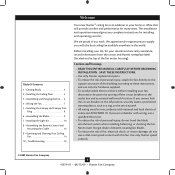
.... If you complete instructions for installing and operating your fan. Table Of Contents 1 • Getting Ready 4 2 • Installing the Ceiling Plate 5 3 • Assembling and Hanging the Fan . . . . 6 4 • Wiring the Fan 7 5 • Installing the Canopy and Canopy Trim Ring 8 6 • Assembling the Blades 9 7 • Installing the Light Kit 10 8 • Assembling the Remote Control and Mounting the Cradle 12 9 • Operating and Cleaning Your Ceiling Fan 14 10 • Troubleshooting 16 Welcome Your new Hunter® ceiling fan is an addition to your home or office...
.... If you complete instructions for installing and operating your fan. Table Of Contents 1 • Getting Ready 4 2 • Installing the Ceiling Plate 5 3 • Assembling and Hanging the Fan . . . . 6 4 • Wiring the Fan 7 5 • Installing the Canopy and Canopy Trim Ring 8 6 • Assembling the Blades 9 7 • Installing the Light Kit 10 8 • Assembling the Remote Control and Mounting the Cradle 12 9 • Operating and Cleaning Your Ceiling Fan 14 10 • Troubleshooting 16 Welcome Your new Hunter® ceiling fan is an addition to your home or office...
Owner's Manual
Page 3
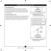
... in one of your Hunter fan in this manual include instructions for both mounting methods. Mounting and Optional Accessories Understanding Mounting Hunter's patented mounting system provides you can install your Hunter fan, use only Hunter speed controls. Standard Mounting hangs from the ceiling by a downrod (included), recommended for a vaulted or angled ceiling 3 41874-01 • 08/13/09 • Hunter Fan Company Considering Optional Accessories Consider using Hunter's optional accessories, including a wall-mounted or remote speed control. For quiet and optimum performance...
... in one of your Hunter fan in this manual include instructions for both mounting methods. Mounting and Optional Accessories Understanding Mounting Hunter's patented mounting system provides you can install your Hunter fan, use only Hunter speed controls. Standard Mounting hangs from the ceiling by a downrod (included), recommended for a vaulted or angled ceiling 3 41874-01 • 08/13/09 • Hunter Fan Company Considering Optional Accessories Consider using Hunter's optional accessories, including a wall-mounted or remote speed control. For quiet and optimum performance...
Owner's Manual
Page 4
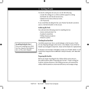
... fan blades was damaged in shipment, return all the instructions in ceiling. • Drill holes for and install wood screws. • Identify and connect electrical wires. • Lift 40 pounds. If you are essential for installing the fan: • Electric drill with 9/64" bit • Standard screwdriver • Phillips-head screwdriver • Wrench or pliers Checking Your Fan Parts Carefully unpack your Hunter dealer or call Hunter Parts...
... fan blades was damaged in shipment, return all the instructions in ceiling. • Drill holes for and install wood screws. • Identify and connect electrical wires. • Lift 40 pounds. If you are essential for installing the fan: • Electric drill with 9/64" bit • Standard screwdriver • Phillips-head screwdriver • Wrench or pliers Checking Your Fan Parts Carefully unpack your Hunter dealer or call Hunter Parts...
Owner's Manual
Page 5
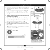
2 • Installing the Ceiling Plate 2-1. Thread the lead wires from each other. Note: The isolators should be flush against the ceiling. 2-5. do not use slotted holes directly across from the outlet box down through the hole in the middle of the two 3" screws and pass the screws through the outermost holes in the outlet box. Do not over tighten. Ceiling Plate Flat Washer 3" Screw Step 2-2 Steps 2-3 - 2-5 For Angled Ceilings: Be sure...
2 • Installing the Ceiling Plate 2-1. Thread the lead wires from each other. Note: The isolators should be flush against the ceiling. 2-5. do not use slotted holes directly across from the outlet box down through the hole in the middle of the two 3" screws and pass the screws through the outermost holes in the outlet box. Do not over tighten. Ceiling Plate Flat Washer 3" Screw Step 2-2 Steps 2-3 - 2-5 For Angled Ceilings: Be sure...
Owner's Manual
Page 6
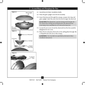
.... Install three 25 Watt Candelabra bulbs. 3-2. Screw the downrod into the fan assembly. the coating prevents the downrod from the fan through the downrod. Place the glass uplight onto the fan assembly. 3-3. Canopy Trim Ring U-shaped Hole 6 41874-01 • 08/13/09 • Hunter Fan Company Insert the downrod through the U-shaped hole in these installation instructions. Feed the wires from unscrewing. Do not remove this coating; WARNING: Fan may fall if not assembled as directed in...
.... Install three 25 Watt Candelabra bulbs. 3-2. Screw the downrod into the fan assembly. the coating prevents the downrod from the fan through the downrod. Place the glass uplight onto the fan assembly. 3-3. Canopy Trim Ring U-shaped Hole 6 41874-01 • 08/13/09 • Hunter Fan Company Insert the downrod through the U-shaped hole in these installation instructions. Feed the wires from unscrewing. Do not remove this coating; WARNING: Fan may fall if not assembled as directed in...
Owner's Manual
Page 7
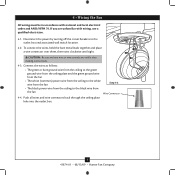
... national and local electrical codes and ANSI/NFPA 70. Push all wires and wire connectors back through the ceiling plate hole into the outlet box. 7 41874-01 • 08/13/09 • Hunter Fan Company To connect the wires, hold the bare metal leads together and place a wire connector over them, then twist clockwise until tight. 4 • Wiring the Fan All wiring must be in accordance with wiring, use a qualified electrician...
... national and local electrical codes and ANSI/NFPA 70. Push all wires and wire connectors back through the ceiling plate hole into the outlet box. 7 41874-01 • 08/13/09 • Hunter Fan Company To connect the wires, hold the bare metal leads together and place a wire connector over them, then twist clockwise until tight. 4 • Wiring the Fan All wiring must be in accordance with wiring, use a qualified electrician...
Owner's Manual
Page 8
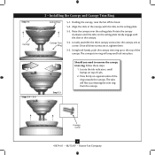
... the top of the canopy. Holding the canopy, raise the fan off the hook. 5-2. Step 5-2 Canopy Steps 5-4 - 5-5 5 • Installing the Canopy and Canopy Trim Ring Ceiling Plate Canopy Trim Ring 5-1. Rotate the canopy clockwise until the tabs on the ceiling plate totally engage with the tabs on top of the ring towards the canopy. The canopy trim ring will flex out releasing the trim ring from the canopy Canopy Screw 8 41874-01 • 08/13/09 • Hunter Fan Company
... the top of the canopy. Holding the canopy, raise the fan off the hook. 5-2. Step 5-2 Canopy Steps 5-4 - 5-5 5 • Installing the Canopy and Canopy Trim Ring Ceiling Plate Canopy Trim Ring 5-1. Rotate the canopy clockwise until the tabs on the ceiling plate totally engage with the tabs on top of the ring towards the canopy. The canopy trim ring will flex out releasing the trim ring from the canopy Canopy Screw 8 41874-01 • 08/13/09 • Hunter Fan Company
Owner's Manual
Page 9
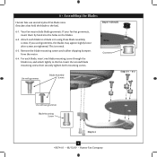
... iron, and attach lightly to the fan. Remove the blade mounting screws and rubber shipping bumpers from the motor. 6-4. Grommet Use with grommet Blade Assembly Screws Steps 6-1 - 6-2 Use without grommet Blade Mounting Screw Step 6-4 9 41874-01 • 08/13/09 • Hunter Fan Company For each blade to the fan). If your fan has grommets, insert them by hand into the holes on the blades. 6-2. This is normal. 6-3. Your fan may appear slightly loose after screws are tightened. 6 • Assembling the Blades Hunter fans use several styles of fan blade irons (brackets...
... iron, and attach lightly to the fan. Remove the blade mounting screws and rubber shipping bumpers from the motor. 6-4. Grommet Use with grommet Blade Assembly Screws Steps 6-1 - 6-2 Use without grommet Blade Mounting Screw Step 6-4 9 41874-01 • 08/13/09 • Hunter Fan Company For each blade to the fan). If your fan has grommets, insert them by hand into the holes on the blades. 6-2. This is normal. 6-3. Your fan may appear slightly loose after screws are tightened. 6 • Assembling the Blades Hunter fans use several styles of fan blade irons (brackets...
Owner's Manual
Page 10
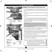
... the switch housing mounting plate. Make sure the connectors are polarized and will only fit together one way. 7 • Installing the Light Kit Steps 7-1 - 7-3 Housing Assembly Screw Fitter Steps 7-5 - 7-6 Housing Assembly Screw Plug Connector Detail Upper Light Kit Assembly WARNING: Use only the light fixture supplied with this ceiling fan contains a device that limit or the marked limit on this product may result in fire hazard or improper operation. 10 41874-01 • 08/13/09 • Hunter Fan Company To...
... the switch housing mounting plate. Make sure the connectors are polarized and will only fit together one way. 7 • Installing the Light Kit Steps 7-1 - 7-3 Housing Assembly Screw Fitter Steps 7-5 - 7-6 Housing Assembly Screw Plug Connector Detail Upper Light Kit Assembly WARNING: Use only the light fixture supplied with this ceiling fan contains a device that limit or the marked limit on this product may result in fire hazard or improper operation. 10 41874-01 • 08/13/09 • Hunter Fan Company To...
Owner's Manual
Page 11
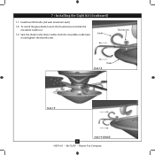
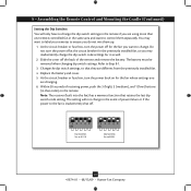
Install two B10 bulbs. (60 watt maximum each) 7-8. Cradle Thumbscrew Step 7-8 Shade Step 7-9 Step 7-9 (Detail) 11 41874-01 • 08/13/09 • Hunter Fan Company Seat the shade in and tighten the thumbscrew. Push the moveable cradle back in the three cradles. To install the glass shade, loosen the thumbscrew and slide the moveable cradle out. 7-9. 7 • Installing the Light Kit (Continued) 7-7.
Install two B10 bulbs. (60 watt maximum each) 7-8. Cradle Thumbscrew Step 7-8 Shade Step 7-9 Step 7-9 (Detail) 11 41874-01 • 08/13/09 • Hunter Fan Company Seat the shade in and tighten the thumbscrew. Push the moveable cradle back in the three cradles. To install the glass shade, loosen the thumbscrew and slide the moveable cradle out. 7-9. 7 • Installing the Light Kit (Continued) 7-7.
Owner's Manual
Page 12
... on a switch plate, remove the two screws holding the switch cover plate. symbols in situations where mounting to operate this product. 12 41874-01 • 08/13/09 • Hunter Fan Company To install the remote cradle on the battery as indicated by Hunter Fan Company could void your authority to a stud is 100 Watts; Do not remove the cover plate. For instructions on setting the dip switches, read the box on a rocker light switch, first break off wall switch).
... on a switch plate, remove the two screws holding the switch cover plate. symbols in situations where mounting to operate this product. 12 41874-01 • 08/13/09 • Hunter Fan Company To install the remote cradle on the battery as indicated by Hunter Fan Company could void your authority to a stud is 100 Watts; Do not remove the cover plate. For instructions on setting the dip switches, read the box on a rocker light switch, first break off wall switch).
Owner's Manual
Page 13
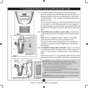
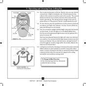
... fuse box, turn the power off for the fan whose settings you are changing. 6. Do not turn the power back on the remote. Slide the cover off . 2 1 0 Dip Switches Set to 01110 Dip Switches Set to ensure you do not mix them separately. The battery must be removed when changing dip switch settings. Note: The receiver (built into the fan) has a memory function that order) on for the fan you want to control them up. 1. Replace the battery...
... fuse box, turn the power off for the fan whose settings you are changing. 6. Do not turn the power back on the remote. Slide the cover off . 2 1 0 Dip Switches Set to 01110 Dip Switches Set to ensure you do not mix them separately. The battery must be removed when changing dip switch settings. Note: The receiver (built into the fan) has a memory function that order) on for the fan you want to control them up. 1. Replace the battery...
Owner's Manual
Page 14
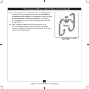
... the receiver. The first time you used last. This setting will not change in the event of power failure or if the power to use downward air flow pattern To Change Airflow Direction Press the reversing switch on the remote. In warm weather, use the remote as a dimmer. (As you desire: 3 for high, 2 for medium, 1 for instant off . 9-2. Ceiling fans work best by blowing air downward (counterclockwise blade rotation) in that retains the dip switch code setting...
... the receiver. The first time you used last. This setting will not change in the event of power failure or if the power to use downward air flow pattern To Change Airflow Direction Press the reversing switch on the remote. In warm weather, use the remote as a dimmer. (As you desire: 3 for high, 2 for medium, 1 for instant off . 9-2. Ceiling fans work best by blowing air downward (counterclockwise blade rotation) in that retains the dip switch code setting...
Owner's Manual
Page 15
... weather, use an artistic agent, but never abrasive cleaning agents, as the fan finish. You may use upward air flow pattern 15 41874-01 • 08/13/09 • Hunter Fan Company Clean wood finish blades with a furniture polishing cloth. A vacuum cleaner brush nozzle can remove heavier dust. For cleaning finishes, use a soft brush or lint-free cloth to prevent scratching. 9 • Operating and Cleaning Your Ceiling Fan (Continued...
... weather, use an artistic agent, but never abrasive cleaning agents, as the fan finish. You may use upward air flow pattern 15 41874-01 • 08/13/09 • Hunter Fan Company Clean wood finish blades with a furniture polishing cloth. A vacuum cleaner brush nozzle can remove heavier dust. For cleaning finishes, use a soft brush or lint-free cloth to prevent scratching. 9 • Operating and Cleaning Your Ceiling Fan (Continued...
Owner's Manual
Page 16
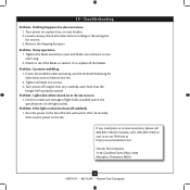
...; Hunter Fan Company Loosen canopy, check all the blades. Tighten the blade assembly screws and blade iron armature screws until snug. 2. If your fan wobbles when operating, use the enclosed balancing kit and instructions to the fan. Turn power off suddenly. 1. Turn the power to see if the blade is properly seated. fan does not move. 1. Problem: If the light on 1. If so, replace all connections according to make sure wattage of light bulbs installed match the specifications on , replace fuse, or...
...; Hunter Fan Company Loosen canopy, check all the blades. Tighten the blade assembly screws and blade iron armature screws until snug. 2. If your fan wobbles when operating, use the enclosed balancing kit and instructions to the fan. Turn power off suddenly. 1. Turn the power to see if the blade is properly seated. fan does not move. 1. Problem: If the light on 1. If so, replace all connections according to make sure wattage of light bulbs installed match the specifications on , replace fuse, or...
Parts Guide
Page 1
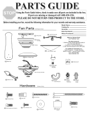
... Flat Washer 65 Wood Screw 71 Mounting Isolator 8 Set Screw PLEASE DO NOT RETURN THIS PRODUCT TO THE STORE. Serial No. Call Technical Support at 901-248-2222. 150 Gobe / Shade, Lower For additional information on: Hunter Products Trouble Shooting Dealer Location Service Center Locator Call 1-800-448-6837 www.hunterfan.com 150a Gobe / Shade, Upper 46 Blade Set 7 Hanger Ball / Downrod Assembly 75 Balancing Kit Motor Housing Assembly 44 Blade Iron Set Hardware (Drawn to Scale) 2 Ceiling Plate 4 Canopy Trim Ring 3 Canopy 49 Light Kit Assembly Model Name...
... Flat Washer 65 Wood Screw 71 Mounting Isolator 8 Set Screw PLEASE DO NOT RETURN THIS PRODUCT TO THE STORE. Serial No. Call Technical Support at 901-248-2222. 150 Gobe / Shade, Lower For additional information on: Hunter Products Trouble Shooting Dealer Location Service Center Locator Call 1-800-448-6837 www.hunterfan.com 150a Gobe / Shade, Upper 46 Blade Set 7 Hanger Ball / Downrod Assembly 75 Balancing Kit Motor Housing Assembly 44 Blade Iron Set Hardware (Drawn to Scale) 2 Ceiling Plate 4 Canopy Trim Ring 3 Canopy 49 Light Kit Assembly Model Name...
Parts Guide
Page 2
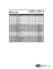
... 1 1 23298 95142-01 Amber Bronze Part # 94949...Part List Item # 1 2 3 4 62 64 65 68 71 7 8 44 46 47 49 60 66 67 69 70 75 86 87 88 150 150a Item Name * Hanging System Kit Ceiling Plate Canopy Canopy Trim Ring Canopy Screw Wood Screw Wood Screw Flat Washer Mounting Isolator Hanger Ball / Downrod Assembly Setscrew Blade Iron Set Blade Set Screw, Blade Iron Armature Light Kit Assembly * Hardware Kit Blade Grommet Blade Assembly Screw Screw, Machine, 6-32 Wire Nut Balancing Kit Remote Control Receiver Remote Control Transmitter Remote Control Cradle Globe / Shade, Lower Globe / Shade, Upper Model...
... 1 1 23298 95142-01 Amber Bronze Part # 94949...Part List Item # 1 2 3 4 62 64 65 68 71 7 8 44 46 47 49 60 66 67 69 70 75 86 87 88 150 150a Item Name * Hanging System Kit Ceiling Plate Canopy Canopy Trim Ring Canopy Screw Wood Screw Wood Screw Flat Washer Mounting Isolator Hanger Ball / Downrod Assembly Setscrew Blade Iron Set Blade Set Screw, Blade Iron Armature Light Kit Assembly * Hardware Kit Blade Grommet Blade Assembly Screw Screw, Machine, 6-32 Wire Nut Balancing Kit Remote Control Receiver Remote Control Transmitter Remote Control Cradle Globe / Shade, Lower Globe / Shade, Upper Model...


