

Installation Guide
Page 1
...wiring must be in the box align with 2 • Installing the Ceiling Plate. o Fan support system will hold full weight of the fan and light kit. Steps 2 - 3 Step 3 Install a Support Brace, If Necessary Determine if there is secured to outlet box by wood screws and washers through ... are unfamiliar with national and local electrical codes and ANSI/NFPA 70. Check the support brace to ensure it is suitable, go to your new Hunter fan. o e outlet box is acceptable and safe for safety, reliable operation, maximum efficiency, and energy savings. o Six inches of 1/...
...wiring must be in the box align with 2 • Installing the Ceiling Plate. o Fan support system will hold full weight of the fan and light kit. Steps 2 - 3 Step 3 Install a Support Brace, If Necessary Determine if there is secured to outlet box by wood screws and washers through ... are unfamiliar with national and local electrical codes and ANSI/NFPA 70. Check the support brace to ensure it is suitable, go to your new Hunter fan. o e outlet box is acceptable and safe for safety, reliable operation, maximum efficiency, and energy savings. o Six inches of 1/...
Owner's Manual
Page 3
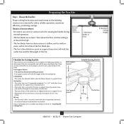
... prepare a new fan site as described on this page. If your new Hunter fan. Fan Support System Fan Support System Suitable Existing Fan Site Wiring Outlet Box 3 42863-01 •...; 06/22/11 • Hunter Fan Company Fan Support System • Fan attaches directly to the joist or support brace by ...approved octagonal 4" x 1-1/2" outlet box (or as walls or posts, within 30 inches of the fan and light kit. Ceiling Hole • The outlet box clearance hole is recessed a minimum of lead wires extend from outlet box...
... prepare a new fan site as described on this page. If your new Hunter fan. Fan Support System Fan Support System Suitable Existing Fan Site Wiring Outlet Box 3 42863-01 •...; 06/22/11 • Hunter Fan Company Fan Support System • Fan attaches directly to the joist or support brace by ...approved octagonal 4" x 1-1/2" outlet box (or as walls or posts, within 30 inches of the fan and light kit. Ceiling Hole • The outlet box clearance hole is recessed a minimum of lead wires extend from outlet box...
Owner's Manual
Page 4
...Step 5 CAUTION: All wiring must be in the off . Position it will use a qualified electrician. 4 42863-01 • 06/22/11 • Hunter Fan Company Install the Outlet Box 4-1. If you are turned off position, securely fasten a prominent warning device, such as follows: 3-1. Make certain the wiring ... pilot holes no larger than the minor diameter of the wood screws (5/64") through the drywall or plaster of the fan and light kit. Locate the site for the ceiling hole directly below the joist or support brace that the fan supply line extends at any hardware...
...Step 5 CAUTION: All wiring must be in the off . Position it will use a qualified electrician. 4 42863-01 • 06/22/11 • Hunter Fan Company Install the Outlet Box 4-1. If you are turned off position, securely fasten a prominent warning device, such as follows: 3-1. Make certain the wiring ... pilot holes no larger than the minor diameter of the wood screws (5/64") through the drywall or plaster of the fan and light kit. Locate the site for the ceiling hole directly below the joist or support brace that the fan supply line extends at any hardware...

Owner's Manual
Page 12
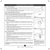
...customize your Hunter fan with the two screws. 7-3. Partially install the third screw and then tighten all three screws securely. 7-5. Connect the upper plug connector from the mounting plate through the gasket. Partially install the gasket to the mounting plate with a number of accessory light kits. Make ...Steps 7-5 - 7-6 Housing Assembly Screw 12 42863-01 • 06/22/11 • Hunter Fan Company Attach the lower switch housing to the upper switch housing with the light fixture. Place the upper switch housing over the two screws and turn counterclockwise so that the screws...
...customize your Hunter fan with the two screws. 7-3. Partially install the third screw and then tighten all three screws securely. 7-5. Connect the upper plug connector from the mounting plate through the gasket. Partially install the gasket to the mounting plate with a number of accessory light kits. Make ...Steps 7-5 - 7-6 Housing Assembly Screw 12 42863-01 • 06/22/11 • Hunter Fan Company Attach the lower switch housing to the upper switch housing with the light fixture. Place the upper switch housing over the two screws and turn counterclockwise so that the screws...


