
Installation Guide
Page 1
.... Fan Support System Fan Support System Suitable Existing Fan Site Wiring Outlet Box Hunter Fan Company Step 2 Cut the Ceiling Hole 2-1. Orient the outlet box so that the fan supply line extends at least 6" beyond the box. 5-3. Attach the outlet box directly to determine if the site is a ceiling joist directly above the floor and the ceiling is at any hardware store or electrical supply house. 4-2. Step 5 Step 5 Prepare the Wiring 5-1. For instructions to install your fan manual...
.... Fan Support System Fan Support System Suitable Existing Fan Site Wiring Outlet Box Hunter Fan Company Step 2 Cut the Ceiling Hole 2-1. Orient the outlet box so that the fan supply line extends at least 6" beyond the box. 5-3. Attach the outlet box directly to determine if the site is a ceiling joist directly above the floor and the ceiling is at any hardware store or electrical supply house. 4-2. Step 5 Step 5 Prepare the Wiring 5-1. For instructions to install your fan manual...

Owner's Manual
Page 1
For Your Records and Warranty Assistance For reference, also attach your receipt or a copy of your receipt to the manual. Model Name Model No. Date Purchased Where Purchased Type 2 Models Owner's Guide and Installation Manual English Español Form# 45030-01 20090911 ©2009 Hunter Fan Co.
For Your Records and Warranty Assistance For reference, also attach your receipt or a copy of your receipt to the manual. Model Name Model No. Date Purchased Where Purchased Type 2 Models Owner's Guide and Installation Manual English Español Form# 45030-01 20090911 ©2009 Hunter Fan Co.
Owner's Manual
Page 2
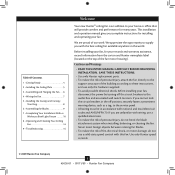
... of our work. We are unfamiliar with wiring, use a solid-state speed control with this fan. Table Of Contents 1 • Getting Ready 4 2 • Installing the Ceiling Plate 5 3 • Assembling and Hanging the Fan . . . . 6 4 • Wiring the Fan 7 5 • Installing the Canopy and Canopy Trim Ring 8 6 • Assembling the Blades 9 7 • Completing Your Installation With or Without a Bowl Light Fixture 10 8 • Operating and Cleaning Your Ceiling Fan 14 9 • Troubleshooting 15 Welcome Your new Hunter® ceiling fan is an addition to the service panel...
... of our work. We are unfamiliar with wiring, use a solid-state speed control with this fan. Table Of Contents 1 • Getting Ready 4 2 • Installing the Ceiling Plate 5 3 • Assembling and Hanging the Fan . . . . 6 4 • Wiring the Fan 7 5 • Installing the Canopy and Canopy Trim Ring 8 6 • Assembling the Blades 9 7 • Completing Your Installation With or Without a Bowl Light Fixture 10 8 • Operating and Cleaning Your Ceiling Fan 14 9 • Troubleshooting 15 Welcome Your new Hunter® ceiling fan is an addition to the service panel...
Owner's Manual
Page 3
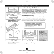
... purchase Hunter extension downrods. All Hunter fans use the accessories, follow the instructions included with each product. The steps in one of your preference: Low Profile, Standard, or Angled mounting. Considering Optional Accessories Consider using Hunter's optional accessories, including a wall-mounted or remote speed control. For quiet and optimum performance of three ways, depending on ceiling height and your Hunter fan, use only the hardware supplied. 3 45030-01 • 09/11/09 • Hunter Fan Company To install and use...
... purchase Hunter extension downrods. All Hunter fans use the accessories, follow the instructions included with each product. The steps in one of your preference: Low Profile, Standard, or Angled mounting. Considering Optional Accessories Consider using Hunter's optional accessories, including a wall-mounted or remote speed control. For quiet and optimum performance of three ways, depending on ceiling height and your Hunter fan, use only the hardware supplied. 3 45030-01 • 09/11/09 • Hunter Fan Company To install and use...
Owner's Manual
Page 4
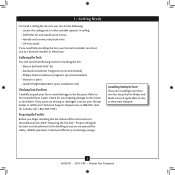
... the instructions in sets, as they were shipped. 4 45030-01 • 09/11/09 • Hunter Fan Company If you need the following : • Locate the ceiling joist or other suitable support in ceiling. • Drill holes for and install wood screws. • Identify and connect electrical wires. • Lift 40 pounds. If any shipping damage to the motor or fan blades. If you are installing more than one fan, keep the fan blades and blade irons...
... the instructions in sets, as they were shipped. 4 45030-01 • 09/11/09 • Hunter Fan Company If you need the following : • Locate the ceiling joist or other suitable support in ceiling. • Drill holes for and install wood screws. • Identify and connect electrical wires. • Lift 40 pounds. If any shipping damage to the motor or fan blades. If you are installing more than one fan, keep the fan blades and blade irons...
Owner's Manual
Page 5
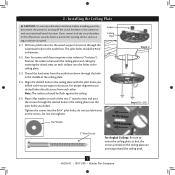
... • Hunter Fan Company Do not over tighten. 2 • Installing the Ceiling Plate CAUTION: To avoid possible electrical shock, before installing your fan, disconnect the power by inserting the raised areas on the screws. Align the slotted holes in the outlet box. Note: The isolators should be flush against the ceiling. 2-5. Isolator Ceiling Plate Flat Washer Step 2-2 Steps 2-3 - 2-5 3" Wood Screw For Angled Ceilings: Be sure to the outlet box and associated wall switch location. Thread...
... • Hunter Fan Company Do not over tighten. 2 • Installing the Ceiling Plate CAUTION: To avoid possible electrical shock, before installing your fan, disconnect the power by inserting the raised areas on the screws. Align the slotted holes in the outlet box. Note: The isolators should be flush against the ceiling. 2-5. Isolator Ceiling Plate Flat Washer Step 2-2 Steps 2-3 - 2-5 3" Wood Screw For Angled Ceilings: Be sure to the outlet box and associated wall switch location. Thread...
Owner's Manual
Page 6
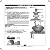
... low profile washer (lip up toward the ceiling. 3-6. Step 3-7 U-shaped Hole Steps 3-2 - 3-3 Downrod Canopy Canopy Trim Ring Setscrew Steps 3-5 - 3-6 Low Profile Washer Low Profile Screw 6 45030-01 • 09/11/09 • Hunter Fan Company Note: When the pipe and ball assembly is normal. For Low Profile mounting: Note: For low profile mounting, the downrod is pointing up ) into the canopy. Be sure the green ground wire is replaced with the holes in the washer with the low profile washer. 3-4. Align the holes in the adapter. 3 • Assembling...
... low profile washer (lip up toward the ceiling. 3-6. Step 3-7 U-shaped Hole Steps 3-2 - 3-3 Downrod Canopy Canopy Trim Ring Setscrew Steps 3-5 - 3-6 Low Profile Washer Low Profile Screw 6 45030-01 • 09/11/09 • Hunter Fan Company Note: When the pipe and ball assembly is normal. For Low Profile mounting: Note: For low profile mounting, the downrod is pointing up ) into the canopy. Be sure the green ground wire is replaced with the holes in the washer with the low profile washer. 3-4. Align the holes in the adapter. 3 • Assembling...
Owner's Manual
Page 7
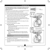
... ceiling to the white wire (grounded) from the fan. 4-4. Wire Connector Dual Switch Wiring Single Switch Wiring 7 45030-01 • 09/11/09 • Hunter Fan Company Before attempting installation, make sure the power is still off. 4-2. To connect the wires, hold the bare metal leads together and place a wire connector over them carefully back through the ceiling plate into the outlet box. 4-7. For all these connections use switch in accordance with national and local electrical codes...
... ceiling to the white wire (grounded) from the fan. 4-4. Wire Connector Dual Switch Wiring Single Switch Wiring 7 45030-01 • 09/11/09 • Hunter Fan Company Before attempting installation, make sure the power is still off. 4-2. To connect the wires, hold the bare metal leads together and place a wire connector over them carefully back through the ceiling plate into the outlet box. 4-7. For all these connections use switch in accordance with national and local electrical codes...
Owner's Manual
Page 8
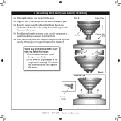
... , tighten them. 5-5. Raise the canopy over the ceiling plate. Rotate the canopy clockwise until the tabs on the ceiling plate. 5-3. Steps 5-4 - 5-5 Ceiling Plate Canopy Trim Ring Step 5-3 Canopy Screw 8 45030-01 • 09/11/09 • Hunter Fan Company Holding the canopy, raise the fan off the hook. 5-2. Partially install the three canopy screws into place. The canopy trim ring will flex out releasing the trim ring from the canopy. Step 5-2 Canopy Should you need to the top of...
... , tighten them. 5-5. Raise the canopy over the ceiling plate. Rotate the canopy clockwise until the tabs on the ceiling plate. 5-3. Steps 5-4 - 5-5 Ceiling Plate Canopy Trim Ring Step 5-3 Canopy Screw 8 45030-01 • 09/11/09 • Hunter Fan Company Holding the canopy, raise the fan off the hook. 5-2. Partially install the three canopy screws into place. The canopy trim ring will flex out releasing the trim ring from the canopy. Step 5-2 Canopy Should you need to the top of...
Owner's Manual
Page 9
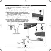
... Company Remove the blade mounting screws and rubber shipping bumpers from the motor. Note: Some blade mounting screws are tightened. 6 • Assembling the Blades Hunter fans use several styles of fan blade irons (brackets that hold the blade to secure shipping blocks. 6-4. If you used grommets, the blades may include blade grommets. Attach each blade, insert one blade mounting screw through the blade iron, and attach lightly to a blade iron using three blade assembly screws. For each blade to the fan. Your fan may appear slightly loose after screws are installed...
... Company Remove the blade mounting screws and rubber shipping bumpers from the motor. Note: Some blade mounting screws are tightened. 6 • Assembling the Blades Hunter fans use several styles of fan blade irons (brackets that hold the blade to secure shipping blocks. 6-4. If you used grommets, the blades may include blade grommets. Attach each blade, insert one blade mounting screw through the blade iron, and attach lightly to a blade iron using three blade assembly screws. For each blade to the fan. Your fan may appear slightly loose after screws are installed...
Owner's Manual
Page 10
... light fixture, you the option of installing the fan with step 7‑6. WARNING: Use only the light fixture supplied with the housing assembly screws. 7-4. Failure to the switch housing mounting plate. If you do not want to uninstall it now. See "Uninstalling the Light Fixture" on step 7-15. Align the keyhole slots in the housing with this fan model. 7-1. Steps 7-1 - 7-3 Housing Assembly Screw Upper Switch Housing 10 45030-01 • 09/11/09 • Hunter Fan Company...
... light fixture, you the option of installing the fan with step 7‑6. WARNING: Use only the light fixture supplied with the housing assembly screws. 7-4. Failure to the switch housing mounting plate. If you do not want to uninstall it now. See "Uninstalling the Light Fixture" on step 7-15. Align the keyhole slots in the housing with this fan model. 7-1. Steps 7-1 - 7-3 Housing Assembly Screw Upper Switch Housing 10 45030-01 • 09/11/09 • Hunter Fan Company...
Owner's Manual
Page 11
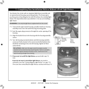
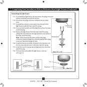
7 • Completing Your Installation With or Without a Bowl Light Fixture (Continued) 7-6. Incorrect connection could cause improper operation and damage to a maximum of 190 Watts. Plug Connector Detail Plug Connector Housing Assembly Screw 11 45030-01 • 09/11/09 • Hunter Fan Company Note: Both plug connectors are properly aligned before connecting them. Steps 7-6 - 7-7 Lower Switch Housing Note: In compliance with three housing assembly screws. Place the lower switch housing assembly over the upper switch housing. Align the side screw holes in fire hazard...
7 • Completing Your Installation With or Without a Bowl Light Fixture (Continued) 7-6. Incorrect connection could cause improper operation and damage to a maximum of 190 Watts. Plug Connector Detail Plug Connector Housing Assembly Screw 11 45030-01 • 09/11/09 • Hunter Fan Company Note: Both plug connectors are properly aligned before connecting them. Steps 7-6 - 7-7 Lower Switch Housing Note: In compliance with three housing assembly screws. Place the lower switch housing assembly over the upper switch housing. Align the side screw holes in fire hazard...
Owner's Manual
Page 12
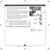
.... Light Bulbs (B10 Candelabra Base 60 Watt Maximum) Metal Rod Metal Disk Breakaway Connector Glass Bowl Cover Plate Finial 12 45030-01 • 09/11/09 • Hunter Fan Company Thread the light pull chain through the finial and screw the finial onto the threaded rod end until tight. Then, Thread the light pull chain throught the hole in the cover plate and glass bowl. 7-14. 7 • Completing Your Installation With or Without a Bowl Light Fixture (Continued) Installing the Glass Bowl 7-8. Attach...
.... Light Bulbs (B10 Candelabra Base 60 Watt Maximum) Metal Rod Metal Disk Breakaway Connector Glass Bowl Cover Plate Finial 12 45030-01 • 09/11/09 • Hunter Fan Company Thread the light pull chain through the finial and screw the finial onto the threaded rod end until tight. Then, Thread the light pull chain throught the hole in the cover plate and glass bowl. 7-14. 7 • Completing Your Installation With or Without a Bowl Light Fixture (Continued) Installing the Glass Bowl 7-8. Attach...
Owner's Manual
Page 13
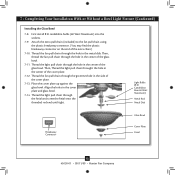
... • Hunter Fan Company Note: When removing the wires, pull the thin plug Threaded Rod connector (male) through first, and then pull the other plug connector (female) through the hole in the lower switch housing. 7-21. 7 • Completing Your Installation With or Without a Bowl Light Fixture (Continued) Uninstalling the Light Fixture 7-15. Unscrew the threaded rod of the light fixture from the end of the lower switch housing. Disconnect the plug connectors between the black wire and the red wire. 7-16. Install the...
... • Hunter Fan Company Note: When removing the wires, pull the thin plug Threaded Rod connector (male) through first, and then pull the other plug connector (female) through the hole in the lower switch housing. 7-21. 7 • Completing Your Installation With or Without a Bowl Light Fixture (Continued) Uninstalling the Light Fixture 7-15. Unscrew the threaded rod of the light fixture from the end of the lower switch housing. Disconnect the plug connectors between the black wire and the red wire. 7-16. Install the...
Owner's Manual
Page 14
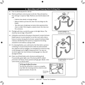
... the chain into the blades. • The chain uses a breakaway connector that separates if the chain is jerked. The light pull chain controls the power to a complete stop. You may use upward air flow pattern To Change Airflow Direction Turn the fan off and let it come to the light fixture. In cold weather, use an artistic agent, but never abrasive cleaning agents as the fan finish. Ceiling fans work best by blowing air downward (counterclockwise blade...
... the chain into the blades. • The chain uses a breakaway connector that separates if the chain is jerked. The light pull chain controls the power to a complete stop. You may use upward air flow pattern To Change Airflow Direction Turn the fan off and let it come to the light fixture. In cold weather, use an artistic agent, but never abrasive cleaning agents as the fan finish. Ceiling fans work best by blowing air downward (counterclockwise blade...
Owner's Manual
Page 15
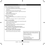
... canopy, check all blade iron screws. 3. Remove the shipping bumpers. If you need parts or service assistance, please call 888‑830‑1326 (In Canada, call 1-866-268-1936) or visit us at our Web site at the wall switch. Tighten the blade assembly screws and blade iron armature screws until snug. 2. If your fan wobbles when operating, use the enclosed balancing kit and instructions to make sure wattage of light bulbs installed match the specifications on...
... canopy, check all blade iron screws. 3. Remove the shipping bumpers. If you need parts or service assistance, please call 888‑830‑1326 (In Canada, call 1-866-268-1936) or visit us at our Web site at the wall switch. Tighten the blade assembly screws and blade iron armature screws until snug. 2. If your fan wobbles when operating, use the enclosed balancing kit and instructions to make sure wattage of light bulbs installed match the specifications on...
Parts Guide
Page 1
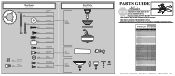
...Parts List Item Name * Canopy Assembly Ceiling Plate Canopy Canopy Trim Ring Hanger Ball / Downrod Assembly Setscrew Low Profile Washer Canopy Screw Wood Screw Wood Screw Flat Washer Mounting Isolator Locking Screw Switch Housing Assembly Cap, Switch Housing Plug Button Blade Iron Set Light Kit Assembly Globe/Shade Cap, Finial Finial Dummy Terminal, Male Dummy Terminal, Female Blade Set Screw, Blade Iron Armature Hardware Kit Blade Grommet Blade Assembly Screw Screw, Machine, 6-32 Wire Connector Screw, Switch Housing Assembly Balancing Kit Pull Chain Pendant Pull Chain Light bulb / Bulb Model...
...Parts List Item Name * Canopy Assembly Ceiling Plate Canopy Canopy Trim Ring Hanger Ball / Downrod Assembly Setscrew Low Profile Washer Canopy Screw Wood Screw Wood Screw Flat Washer Mounting Isolator Locking Screw Switch Housing Assembly Cap, Switch Housing Plug Button Blade Iron Set Light Kit Assembly Globe/Shade Cap, Finial Finial Dummy Terminal, Male Dummy Terminal, Female Blade Set Screw, Blade Iron Armature Hardware Kit Blade Grommet Blade Assembly Screw Screw, Machine, 6-32 Wire Connector Screw, Switch Housing Assembly Balancing Kit Pull Chain Pendant Pull Chain Light bulb / Bulb Model...


