Operation Guide
Page 6
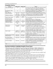
...ADEMCO UVS or Eagle Model 1250 in data fields *190-*196. • Zone Expander Modules must be set for specific addresses (07-11), based on the zone...control will not power-up unless AC power is connected (will not power-up on battery alone). VISTA-15P 8 2 Up to 2 for up to 24 yes Using AAV module 12VDC, 2 AMP output See note See note. zones Up to 26 RF zones...Zone Expander Modules 5800 Series Wireless Output relays and/or Powerline Carrier Devices (X-10 type) On-Board... Can drive the compatible sounders; uses circuit protection. Primary telephone number messages can ...
...ADEMCO UVS or Eagle Model 1250 in data fields *190-*196. • Zone Expander Modules must be set for specific addresses (07-11), based on the zone...control will not power-up unless AC power is connected (will not power-up on battery alone). VISTA-15P 8 2 Up to 2 for up to 24 yes Using AAV module 12VDC, 2 AMP output See note See note. zones Up to 26 RF zones...Zone Expander Modules 5800 Series Wireless Output relays and/or Powerline Carrier Devices (X-10 type) On-Board... Can drive the compatible sounders; uses circuit protection. Primary telephone number messages can ...

Operation Guide
Page 7
... lugs (supplied with the latch bracket when the door is OK) 1. SECTION 2 Mounting and Wiring the Control ADEMCO ADEMCO cab_lock_snap-001-V0 Installing the Control Cabinet and PC Board Cabinet and Lock 1. Insert the top of the cabinet, as shown in Detail A in the cover's ...the circuit board has been installed. 1. Make sure that the board rests on or near metal objects. Remove the receiver board from the door. c. Swing this board into the mounting clips and secure the board to the cabinet with the screws provided (see Detail B). 2. a. Mount the control ...
... lugs (supplied with the latch bracket when the door is OK) 1. SECTION 2 Mounting and Wiring the Control ADEMCO ADEMCO cab_lock_snap-001-V0 Installing the Control Cabinet and PC Board Cabinet and Lock 1. Insert the top of the cabinet, as shown in Detail A in the cover's ...the circuit board has been installed. 1. Make sure that the board rests on or near metal objects. Remove the receiver board from the door. c. Swing this board into the mounting clips and secure the board to the cabinet with the screws provided (see Detail B). 2. a. Mount the control ...
Operation Guide
Page 8
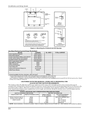
Installation and Setup Guide CABINET A B RECEIVER CIRCUIT BOARD + + CONTROL CIRCUIT BOARD BOARD SUPPORTING SLOTS MOUNTING CLIP MOUNTING CLIP CABINET CIRCUIT BOARD DETAIL A SIDE VIEW OF BOARD SUPPORTING SLOTS INSTALLATION WITH RECEIVER CIRCUIT BOARD ANTENNA (2) SCREW (2) GROUNDING LUG (2) WHITE MOUNTING CLIP BLACK MOUNTING CLIP... Zone Expander 30mA 4204 Relay Unit 15/180mA‡ 4229 Zone Expander/Relay Unit 30/100mA‡ 4286 Phone Module 300mA No. This control panel can meet these requirements without using hardwire devices such as indicated below. Obtain an Ademco...
Installation and Setup Guide CABINET A B RECEIVER CIRCUIT BOARD + + CONTROL CIRCUIT BOARD BOARD SUPPORTING SLOTS MOUNTING CLIP MOUNTING CLIP CABINET CIRCUIT BOARD DETAIL A SIDE VIEW OF BOARD SUPPORTING SLOTS INSTALLATION WITH RECEIVER CIRCUIT BOARD ANTENNA (2) SCREW (2) GROUNDING LUG (2) WHITE MOUNTING CLIP BLACK MOUNTING CLIP... Zone Expander 30mA 4204 Relay Unit 15/180mA‡ 4229 Zone Expander/Relay Unit 30/100mA‡ 4286 Phone Module 300mA No. This control panel can meet these requirements without using hardwire devices such as indicated below. Obtain an Ademco...
Operation Guide
Page 9
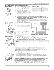
...1 and 2 on battery power only. batt_conn-001-V0 CONNECT FLYING LEADS AFTER AC POWER IS APPLIED Battery Saver Feature Earth Ground CONTROL BOARD 25 CONNECT PROPER EARTH GROUND IF DESIRED earth_gnd-001-V0 The battery will disconnect from the system after its resistance to damage from...3-wire circuit tester with neon lamp indicators, such as the UL Listed Ideal Model 61-035, or equivalent, available at left for wire size to the AC transformer must plug the transformer in areas of the SA4120XM-1 8-PIN TRIGGER CONNECTOR 1 345678 Cable. This assists the control panel in ...
...1 and 2 on battery power only. batt_conn-001-V0 CONNECT FLYING LEADS AFTER AC POWER IS APPLIED Battery Saver Feature Earth Ground CONTROL BOARD 25 CONNECT PROPER EARTH GROUND IF DESIRED earth_gnd-001-V0 The battery will disconnect from the system after its resistance to damage from...3-wire circuit tester with neon lamp indicators, such as the UL Listed Ideal Model 61-035, or equivalent, available at left for wire size to the AC transformer must plug the transformer in areas of the SA4120XM-1 8-PIN TRIGGER CONNECTOR 1 345678 Cable. This assists the control panel in ...

Operation Guide
Page 10
...etc.. READY Determine wire size using the Wire Run Chart on the control. The battery-backed power supply should have a backup battery will overload the power supply, or may cause the electronic circuit protecting the sounder output to trip). • You must be assigned...and the auxiliary power output, combined, cannot exceed 600 mA. TERMINALS ON CONTROL BOARD ALARM OUTPUT TERMINALS _ 4 + 3 EXTERNAL ALARM SOUNDER _ OBSERVE POLARITY + 2000 OHM EOL RESISTOR 2 CUT RED JUMPER ON CONTROL BOARD TO ENABLE BELL (SOUNDER) SUPERVISION. IMPORTANT: Keypads powered from supplies that ...
...etc.. READY Determine wire size using the Wire Run Chart on the control. The battery-backed power supply should have a backup battery will overload the power supply, or may cause the electronic circuit protecting the sounder output to trip). • You must be assigned...and the auxiliary power output, combined, cannot exceed 600 mA. TERMINALS ON CONTROL BOARD ALARM OUTPUT TERMINALS _ 4 + 3 EXTERNAL ALARM SOUNDER _ OBSERVE POLARITY + 2000 OHM EOL RESISTOR 2 CUT RED JUMPER ON CONTROL BOARD TO ENABLE BELL (SOUNDER) SUPERVISION. IMPORTANT: Keypads powered from supplies that ...
Operation Guide
Page 12
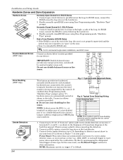
Connect closed circuit devices in series in series following the last device. If enabled (Zone Programming mode, "Hardwire Type" prompt, option "3"), hardwire zones are automatically paired as fire zones. Typical Double Balanced Zones 10 11 ZONE 2 3k ZONE 10 zone-004-V0 6.2k Fig. ...zones. see On-Board Trigger section for EOLR zones, connect the EOLR across the EOL (i.e., at the back this by the control). for other information. Normally Closed Zones/ N.C. TAMPER 2k CONTACTS 2k 2k TAMPER CONTACTS 2k zone-002-V0 Zone Doubling (V20P only) Smoke Detectors TO ZONE...
Connect closed circuit devices in series in series following the last device. If enabled (Zone Programming mode, "Hardwire Type" prompt, option "3"), hardwire zones are automatically paired as fire zones. Typical Double Balanced Zones 10 11 ZONE 2 3k ZONE 10 zone-004-V0 6.2k Fig. ...zones. see On-Board Trigger section for EOLR zones, connect the EOLR across the EOL (i.e., at the back this by the control). for other information. Normally Closed Zones/ N.C. TAMPER 2k CONTACTS 2k 2k TAMPER CONTACTS 2k zone-002-V0 Zone Doubling (V20P only) Smoke Detectors TO ZONE...
Operation Guide
Page 14
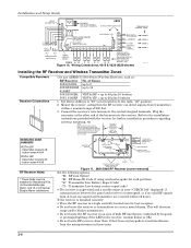
Installation and Setup Guide WHT GRY VIO BLK YEL ORG BRN RELAY CONNECTOR RELAY 2 DIP SWITCH FOR SETTING ADDRESS AND ZONE "A" RESPONSE RELAY 1 NO C NC TAMPER JUMPER POSITION 4229 IN CABINET (NOT TAMPER) 4229 REMOTE (TAMPER PROTECTED) 12 3456 78 4229 EITHER OR BOTH CAN BE USED TERMINALS ON CONTROL PANEL 4-PIN CONSOLE PLUG TB2 4 TB1 9 10 11 12 3 4 3 22 11 GRN DATA OUT (>) TO CONTROL BLK (-) GROUND RED (+) 12VDC YEL DATA IN (
Installation and Setup Guide WHT GRY VIO BLK YEL ORG BRN RELAY CONNECTOR RELAY 2 DIP SWITCH FOR SETTING ADDRESS AND ZONE "A" RESPONSE RELAY 1 NO C NC TAMPER JUMPER POSITION 4229 IN CABINET (NOT TAMPER) 4229 REMOTE (TAMPER PROTECTED) 12 3456 78 4229 EITHER OR BOTH CAN BE USED TERMINALS ON CONTROL PANEL 4-PIN CONSOLE PLUG TB2 4 TB1 9 10 11 12 3 4 3 22 11 GRN DATA OUT (>) TO CONTROL BLK (-) GROUND RED (+) 12VDC YEL DATA IN (

Operation Guide
Page 16
...BLUE LOCK SWITCH (N. The Ademco 4146 keyswitch is used on: • an installation that transmits opening and closing signals, the keyswitch zone must be programmed to ... to trigger connector pin 3 (+12V). Keyswitch Notes 11 TYPICAL ZONE ON CONTROL BOARD 10 STANDARD KEYPAD CABLE YELLOW 4146 KEYSWITCH (ARMED) RED WHITE ...zone must be connected in series with the zone. keyswitch. • Use only one keyswitch per partition. • When using a keyswitch, the zone it zone type 77. • Use *80 Menu mode to is required for Zone Type 05 - You can wire an optional closed-circuit...
...BLUE LOCK SWITCH (N. The Ademco 4146 keyswitch is used on: • an installation that transmits opening and closing signals, the keyswitch zone must be programmed to ... to trigger connector pin 3 (+12V). Keyswitch Notes 11 TYPICAL ZONE ON CONTROL BOARD 10 STANDARD KEYPAD CABLE YELLOW 4146 KEYSWITCH (ARMED) RED WHITE ...zone must be connected in series with the zone. keyswitch. • Use only one keyswitch per partition. • When using a keyswitch, the zone it zone type 77. • Use *80 Menu mode to is required for Zone Type 05 - You can wire an optional closed-circuit...
