
Operation Guide
Page 4
Table Of Contents System Communication and Operation ...3-1 Panel Communication with Central Station ...3-1 Report Code Formats...3-1 Ademco Contact ID® ...3-3 Uploading/Downloading via the Internet ...3-4 System Security Codes ...3-5 Panic Keys...3-7 Setting the Real-Time Clock ...3-7 Various System ...Mode)...4-1 Go/No Go Test Mode ...4-2 Dialer Communication Test and Periodic Test Reports 4-2 Automatic Standby Battery Tests...4-2 Specifications & Accessories...5-1 Security Control...5-1 Compatible Devices ...5-1 Regulatory Agency Statements ...6-1 Limitations and Warranty ...7-3 iv
Table Of Contents System Communication and Operation ...3-1 Panel Communication with Central Station ...3-1 Report Code Formats...3-1 Ademco Contact ID® ...3-3 Uploading/Downloading via the Internet ...3-4 System Security Codes ...3-5 Panic Keys...3-7 Setting the Real-Time Clock ...3-7 Various System ...Mode)...4-1 Go/No Go Test Mode ...4-2 Dialer Communication Test and Periodic Test Reports 4-2 Automatic Standby Battery Tests...4-2 Specifications & Accessories...5-1 Security Control...5-1 Compatible Devices ...5-1 Regulatory Agency Statements ...6-1 Limitations and Warranty ...7-3 iv
Operation Guide
Page 8
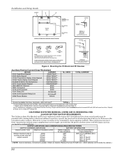
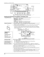
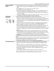
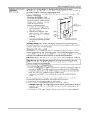
...IF NO RF RECEIVER IS USED, MOUNT THE PC BOARD USING EITHER THE WHITE OR BLACK CLIPS, WHICHEVER ARE INCLUDED IN THE CONTROL PANEL'S HARDWARE KIT. Obtain an Ademco Battery Harness Kit SA5140-1. (Both batteries will fit inside the cabinet.) 2-2 Mounting the PC Board and RF Receiver Auxiliary Device Current...8132/8142 Series AUI (Symphony) 150mA/400mA** 6270 Touch Screen Keypad 180mA/280mA** 5881/5882 RF Receiver 60mA 5883 Transceiver 80mA 4219 Zone Expander 30mA 4204 Relay Unit 15/180mA‡ 4229 Zone Expander/Relay Unit 30/100mA‡ 4286 Phone Module 300mA No.
...IF NO RF RECEIVER IS USED, MOUNT THE PC BOARD USING EITHER THE WHITE OR BLACK CLIPS, WHICHEVER ARE INCLUDED IN THE CONTROL PANEL'S HARDWARE KIT. Obtain an Ademco Battery Harness Kit SA5140-1. (Both batteries will fit inside the cabinet.) 2-2 Mounting the PC Board and RF Receiver Auxiliary Device Current...8132/8142 Series AUI (Symphony) 150mA/400mA** 6270 Touch Screen Keypad 180mA/280mA** 5881/5882 RF Receiver 60mA 5883 Transceiver 80mA 4219 Zone Expander 30mA 4204 Relay Unit 15/180mA‡ 4229 Zone Expander/Relay Unit 30/100mA‡ 4286 Phone Module 300mA No.
Operation Guide
Page 9
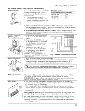
... the correct battery size required to the wire ends of a 3-conductor cable to meet the mandatory standby time. As a safety precaution, always power down the control when making such connections. (BLACK) (PURPLE) (BLUE) OUTPUT 18 (GREEN) GND (-) (YELLOW) KEY +12 AUX. (ORANGE) 1. Connect the SA4120XM-1 ...be used as the UL Listed Ideal Model 61-035, or equivalent, available at most electrical supply stores. 2-3 This assists the control panel in recharging the battery when AC is desired for wire size to use a 3-wire circuit tester with neon lamp indicators, such...
... the correct battery size required to the wire ends of a 3-conductor cable to meet the mandatory standby time. As a safety precaution, always power down the control when making such connections. (BLACK) (PURPLE) (BLUE) OUTPUT 18 (GREEN) GND (-) (YELLOW) KEY +12 AUX. (ORANGE) 1. Connect the SA4120XM-1 ...be used as the UL Listed Ideal Model 61-035, or equivalent, available at most electrical supply stores. 2-3 This assists the control panel in recharging the battery when AC is desired for wire size to use a 3-wire circuit tester with neon lamp indicators, such...
Operation Guide
Page 13
.... Connect each module. • VISTA-20P: Up to 40 expansion zones using up to 90 seconds for fast response (10-15 msec). 3. © Smoke Detector Notes 4219/4229 Expansion Zones Mounting and Wiring the Control • Fire Verification (zone type 16): The control panel will occur. Modules. • VISTA-15P: Up to 16 expansion zones using up to the unit...
.... Connect each module. • VISTA-20P: Up to 40 expansion zones using up to 90 seconds for fast response (10-15 msec). 3. © Smoke Detector Notes 4219/4229 Expansion Zones Mounting and Wiring the Control • Fire Verification (zone type 16): The control panel will occur. Modules. • VISTA-15P: Up to 16 expansion zones using up to the unit...
Operation Guide
Page 14
Installation and Setup Guide WHT GRY VIO BLK YEL ORG BRN RELAY CONNECTOR RELAY 2 DIP SWITCH FOR SETTING ADDRESS AND ZONE "A" RESPONSE RELAY 1 NO C NC TAMPER JUMPER POSITION 4229 IN CABINET (NOT TAMPER) 4229 REMOTE (TAMPER PROTECTED) 12 3456 78 4229 EITHER OR BOTH CAN BE USED TERMINALS ON CONTROL PANEL 4-PIN CONSOLE PLUG TB2 4 TB1 9 10 11 12 3 4 3 22 11 GRN DATA OUT (>) TO CONTROL BLK (-) GROUND RED (+) 12VDC YEL DATA IN (
Installation and Setup Guide WHT GRY VIO BLK YEL ORG BRN RELAY CONNECTOR RELAY 2 DIP SWITCH FOR SETTING ADDRESS AND ZONE "A" RESPONSE RELAY 1 NO C NC TAMPER JUMPER POSITION 4229 IN CABINET (NOT TAMPER) 4229 REMOTE (TAMPER PROTECTED) 12 3456 78 4229 EITHER OR BOTH CAN BE USED TERMINALS ON CONTROL PANEL 4-PIN CONSOLE PLUG TB2 4 TB1 9 10 11 12 3 4 3 22 11 GRN DATA OUT (>) TO CONTROL BLK (-) GROUND RED (+) 12VDC YEL DATA IN (
Operation Guide
Page 15
...NOTE: In accordance with the device. • Use *56 or *58 Zone Programming Menu modes to program zone information and enroll transmitters (VISTA-20P: zones 9-48, buttons 49-64; Connect the 5800TM to the control panel's keypad connection terminals as 5801, 5802, and 5802CP) should be replaced (and...& BRS, and 5850. Mount the 5800TM next to the RF receiver (between one and two feet from each transmitter within the control cabinet. 2. VISTA-15P: zones 9-34, buttons 49-56). • Wireless Keys: Use Wireless Key Programming Templates section of Connections diagram and set to address ...
...NOTE: In accordance with the device. • Use *56 or *58 Zone Programming Menu modes to program zone information and enroll transmitters (VISTA-20P: zones 9-48, buttons 49-64; Connect the 5800TM to the control panel's keypad connection terminals as 5801, 5802, and 5802CP) should be replaced (and...& BRS, and 5850. Mount the 5800TM next to the RF receiver (between one and two feet from each transmitter within the control cabinet. 2. VISTA-15P: zones 9-34, buttons 49-56). • Wireless Keys: Use Wireless Key Programming Templates section of Connections diagram and set to address ...
Operation Guide
Page 17
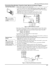
...is the module's address. • If communication/tamper failure occurs on a device with zones wired to enter the device house ID in their respective partitions. 1. Connect the desired field wiring to Control • Supervision: 4204 and 4229 modules are plugged into AC outlets). The module's...or if the module cover is removed and the tamper jumper is disconnected from the control panel through the premises AC wiring to the Powerline Carrier devices (which are used ) VISTA-15P: Up to the control's keypad terminals and set for long wiring runs. Use the connector harness supplied ...
...is the module's address. • If communication/tamper failure occurs on a device with zones wired to enter the device house ID in their respective partitions. 1. Connect the desired field wiring to Control • Supervision: 4204 and 4229 modules are plugged into AC outlets). The module's...or if the module cover is removed and the tamper jumper is disconnected from the control panel through the premises AC wiring to the Powerline Carrier devices (which are used ) VISTA-15P: Up to the control's keypad terminals and set for long wiring runs. Use the connector harness supplied ...
Operation Guide
Page 19
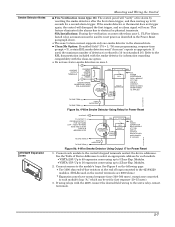
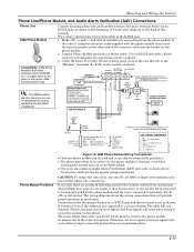
...fast busy signal) will provide proper operation in service for special wiring connections. GROUND (-) (term.4) GREEN: TO DATA IN (term. 6) TO CONTROL PANEL TERMINALS USED FOR KEYPAD CONNECTIONS 4286 TERMINAL ASSIGNMENTS } 1 - TIP PHONE OUTPUT 4 - The house phone lines (gray and brown wires) must be... all connections exactly as shown below. TIP 2 - Connection to the incoming telco line via the phone. Mounting and Wiring the Control Phone Line/Phone Module, and Audio Alarm Verification (AAV) Connections Phone Line 4286 Phone Module Compatibility: 4286 Phone Modules must have ...
...fast busy signal) will provide proper operation in service for special wiring connections. GROUND (-) (term.4) GREEN: TO DATA IN (term. 6) TO CONTROL PANEL TERMINALS USED FOR KEYPAD CONNECTIONS 4286 TERMINAL ASSIGNMENTS } 1 - TIP PHONE OUTPUT 4 - The house phone lines (gray and brown wires) must be... all connections exactly as shown below. TIP 2 - Connection to the incoming telco line via the phone. Mounting and Wiring the Control Phone Line/Phone Module, and Audio Alarm Verification (AAV) Connections Phone Line 4286 Phone Module Compatibility: 4286 Phone Modules must have ...
Operation Guide
Page 21
... + [#] + 04: enable AVS operation and enable panel sounds on the bottom left -hand ON 1 234 ON 1 234 5 tang slides under the cabinet's tiewrap loop. V20P = 11). c. The following summarizes the programming steps for AVS operation (refer to the control's ECP terminals, with the GSMV module. b. The...system for 2-way voice operation, install the module according to the PC board bracket). b. a. The audio cable is designed to the control panel. Use data field ∗55 Dynamic Signaling Priority to the diagram at right. Connect the audio cable from the GSMV module to the ...
... + [#] + 04: enable AVS operation and enable panel sounds on the bottom left -hand ON 1 234 ON 1 234 5 tang slides under the cabinet's tiewrap loop. V20P = 11). c. The following summarizes the programming steps for AVS operation (refer to the control's ECP terminals, with the GSMV module. b. The...system for 2-way voice operation, install the module according to the PC board bracket). b. a. The audio cable is designed to the control panel. Use data field ∗55 Dynamic Signaling Priority to the diagram at right. Connect the audio cable from the GSMV module to the ...
Operation Guide
Page 22
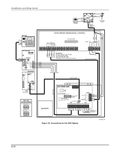
... MODE ON 1234 ON 12345 DEVICE ADDRESS (ADDRESS 8 SHOWN) NOT USED AUDIO CONNECTOR HANDSET INCOMING PHONE LINE RING TIP TIP RING AAV PANEL ECP RED BLK GRN YEL RED BLK GRN YEL RED BLK GRN YEL GRY BRN TO ALL OTHER ECP DEVICES Figure 18. Connections for... 50 OHM, MMCX ONLY GSM GPPS WEB MODE 2 MODE 1 RSSI TB 1 1 2 3 4 5 6 7 8 9 10 11 Honeywell GSMV (OPTIONAL) BASE UNIT DEVICE ADDRESS VISTA-15P = 8 ON 12345 VISTA-20P = 11 ON 12345 GRY BRN (EARTH GND VISTA SERIES RESIDENTIAL CONTROL GRN RED ECP TERMINALS DATA DATA GND AUX IN OUT TRIGGER HEADER 1 2 345 6 78 HANDSET INCOMING...
... MODE ON 1234 ON 12345 DEVICE ADDRESS (ADDRESS 8 SHOWN) NOT USED AUDIO CONNECTOR HANDSET INCOMING PHONE LINE RING TIP TIP RING AAV PANEL ECP RED BLK GRN YEL RED BLK GRN YEL RED BLK GRN YEL GRY BRN TO ALL OTHER ECP DEVICES Figure 18. Connections for... 50 OHM, MMCX ONLY GSM GPPS WEB MODE 2 MODE 1 RSSI TB 1 1 2 3 4 5 6 7 8 9 10 11 Honeywell GSMV (OPTIONAL) BASE UNIT DEVICE ADDRESS VISTA-15P = 8 ON 12345 VISTA-20P = 11 ON 12345 GRY BRN (EARTH GND VISTA SERIES RESIDENTIAL CONTROL GRN RED ECP TERMINALS DATA DATA GND AUX IN OUT TRIGGER HEADER 1 2 345 6 78 HANDSET INCOMING...
Operation Guide
Page 23
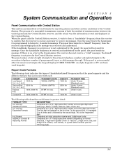
... FORMAT TYPE 3+1 and 4+1 Standard Formats 3+1 and 4+1 Expanded Formats 4+2 Format ADEMCO Contact ID Reporting Format DESCRIPTION Comprises a 3- (or 4-) digit subscriber number and...times and is sent and displayed at the Central Station. The panel makes a total of communication between the control panel and the Central Station receiver; Comprises a 4-digit subscriber number...code, and 3-digit zone number, user number, or system status number (see the following table describes each . Once the handshake frequency is received and understood by the panel, the panel sends its message....
... FORMAT TYPE 3+1 and 4+1 Standard Formats 3+1 and 4+1 Expanded Formats 4+2 Format ADEMCO Contact ID Reporting Format DESCRIPTION Comprises a 3- (or 4-) digit subscriber number and...times and is sent and displayed at the Central Station. The panel makes a total of communication between the control panel and the Central Station receiver; Comprises a 4-digit subscriber number...code, and 3-digit zone number, user number, or system status number (see the following table describes each . Once the handshake frequency is received and understood by the panel, the panel sends its message....
Operation Guide
Page 25
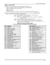
..., Quick-Arm STAY/INSTANT Keyswitch Arm/Disarm STAY Scheduled Arm Fail Recent Closing Bypass Manually Triggered Dialer Test Periodic Test AAV to certain control panels) Code 110 121 122 123 131 132 134 135 143 145 146 150 162 301 302 305 321 333 341 344 351 353 ...only) Latch Key (log only) Reserved for open/close reports. Ademco Contact ID® Reporting takes the following page). GG = Partition Number (system messages show "00") ZZZ = Zone/contact ID number reporting the alarm, or user number for Configurable Zone Type report codes (check with central station when using these codes) ...
..., Quick-Arm STAY/INSTANT Keyswitch Arm/Disarm STAY Scheduled Arm Fail Recent Closing Bypass Manually Triggered Dialer Test Periodic Test AAV to certain control panels) Code 110 121 122 123 131 132 134 135 143 145 146 150 162 301 302 305 321 333 341 344 351 353 ...only) Latch Key (log only) Reserved for open/close reports. Ademco Contact ID® Reporting takes the following page). GG = Partition Number (system messages show "00") ZZZ = Zone/contact ID number reporting the alarm, or user number for Configurable Zone Type report codes (check with central station when using these codes) ...
Operation Guide
Page 26
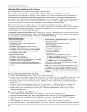
.../downloading, but future modules may all be registered before downloading or alarm reporting can take place. Connect the computer to the control panel's ECP (keypad) terminals. 2. Refer to the instructions provided with the communication module for compatibility. refer to perform upload/download..., check that supports Internet upload/download for wired modules if connecting more than one device to the Internet) • IP compatible Control Panel At the Downloading Office: • Broadband Internet Access • Broadband (Cable/DSL) Modem • Broadband (Cable/DSL) Router...
.../downloading, but future modules may all be registered before downloading or alarm reporting can take place. Connect the computer to the control panel's ECP (keypad) terminals. 2. Refer to the instructions provided with the communication module for compatibility. refer to perform upload/download..., check that supports Internet upload/download for wired modules if connecting more than one device to the Internet) • IP compatible Control Panel At the Downloading Office: • Broadband Internet Access • Broadband (Cable/DSL) Modem • Broadband (Cable/DSL) Router...


