Installation Instructions
Page 3
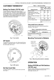
... F position. FUEL SWITCH Fig. 7. Table 2. OPERATION Setting SYSTEM and FAN Switches (T8775C only) System and fan settings are controlled manually by using the switches located at the factory in a system where the G terminal is connected. Fuel switch. M19497 DIP Switch To.... DIP switch. M19498 Fig. 9. Heat Cycle Rate. Set Heat Cycle Rate Use DIP switches 1 and 2 to wallplate. T8775A,C THE DIGITAL ROUND™ NON-PROGRAMMABLE THERMOSTATS CUSTOMIZE THERMOSTAT Setting Fuel Switch (T8775C only) The fuel switch is preset at the top of the thermostat. Mounting ...
... F position. FUEL SWITCH Fig. 7. Table 2. OPERATION Setting SYSTEM and FAN Switches (T8775C only) System and fan settings are controlled manually by using the switches located at the factory in a system where the G terminal is connected. Fuel switch. M19497 DIP Switch To.... DIP switch. M19498 Fig. 9. Heat Cycle Rate. Set Heat Cycle Rate Use DIP switches 1 and 2 to wallplate. T8775A,C THE DIGITAL ROUND™ NON-PROGRAMMABLE THERMOSTATS CUSTOMIZE THERMOSTAT Setting Fuel Switch (T8775C only) The fuel switch is preset at the top of the thermostat. Mounting ...


