
Owner's Manual
Page 1
All Rights Reserved 69-1679EF-1 Registered Trademark Patents Pending © 2004 Honeywell International Inc. T8775A,C The Digital Round™ Non-Programmable Thermostats OWNER'S GUIDE ® U.S.
All Rights Reserved 69-1679EF-1 Registered Trademark Patents Pending © 2004 Honeywell International Inc. T8775A,C The Digital Round™ Non-Programmable Thermostats OWNER'S GUIDE ® U.S.
Owner's Manual
Page 2
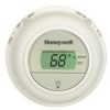
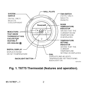
DISPLAYS AND ADJUSTS TEMPERATURE SETTING/TURNS BACKLIGHT ON M19470 Fig. 1. DISPLAYS ROOM OR SET TEMPERATURE SHOWS THAT THE CURRENT TEMPERATURE SETTING IS DISPLAYED. T8775 Thermostat (features and operation). 69-1679EF-1 2 (T8775C ONLY) SELECTS COOL/OFF/HEAT (T8775C ONLY) SELECTS ON/AUTO ROOM SHOWS THAT THE SET CURRENT ROOM TEMPERATURE IS DISPLAYED.
DISPLAYS AND ADJUSTS TEMPERATURE SETTING/TURNS BACKLIGHT ON M19470 Fig. 1. DISPLAYS ROOM OR SET TEMPERATURE SHOWS THAT THE CURRENT TEMPERATURE SETTING IS DISPLAYED. T8775 Thermostat (features and operation). 69-1679EF-1 2 (T8775C ONLY) SELECTS COOL/OFF/HEAT (T8775C ONLY) SELECTS ON/AUTO ROOM SHOWS THAT THE SET CURRENT ROOM TEMPERATURE IS DISPLAYED.
Owner's Manual
Page 3
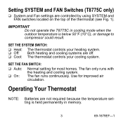
SET THE FAN SWITCH: ❑ Auto: Normal setting for improved air circulation. SET THE SYSTEM SWITCH: ❑ Heat: The thermostat controls your cooling system. Use for most homes. IMPORTANT Do not operate the T8775C in memory. 3 69-1679EF-1 The fan runs continuously. The fan only runs with ❑ On: the heating and cooling system. Setting SYSTEM and FAN Switches (T8775C only) ❑ System and Fan settings are off. ❑ Cool: The thermostat controls your heating system. ❑ Off: Both heating and cooling systems...
SET THE FAN SWITCH: ❑ Auto: Normal setting for improved air circulation. SET THE SYSTEM SWITCH: ❑ Heat: The thermostat controls your cooling system. Use for most homes. IMPORTANT Do not operate the T8775C in memory. 3 69-1679EF-1 The fan runs continuously. The fan only runs with ❑ On: the heating and cooling system. Setting SYSTEM and FAN Switches (T8775C only) ❑ System and Fan settings are off. ❑ Cool: The thermostat controls your heating system. ❑ Off: Both heating and cooling systems...
Owner's Manual
Page 4
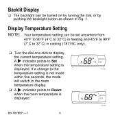
... the temperature setting is displayed. If a change to the temperature setting is not made within five seconds, the mode will switch to the room temperature display. ❑ A indicator points to Room when the room temperature is displayed. Backlit Display ❑ The backlight can be turned on by turning the dial, or by pushing the backlight button as shown in cooling (T8775C only). ❑ Turn the dial one click to display the current temperature setting.
... the temperature setting is displayed. If a change to the temperature setting is not made within five seconds, the mode will switch to the room temperature display. ❑ A indicator points to Room when the room temperature is displayed. Backlit Display ❑ The backlight can be turned on by turning the dial, or by pushing the backlight button as shown in cooling (T8775C only). ❑ Turn the dial one click to display the current temperature setting.
Owner's Manual
Page 5
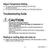
... temperature is set to compressor or other equipment. Heating or cooling does not come on. ❑ Make sure that the SYSTEM switch on the thermostat is below 50°F (10°C). Can cause permanent damage to Heat or Cool (T8775C only). 5 69-1679EF-1 Allow compressor to remain off for five minutes before restarting. Troubleshooting Guide CAUTION Equipment Damage Hazard. Adjust Temperature Setting ❑ To lower the temperature setting, turn...
... temperature is set to compressor or other equipment. Heating or cooling does not come on. ❑ Make sure that the SYSTEM switch on the thermostat is below 50°F (10°C). Can cause permanent damage to Heat or Cool (T8775C only). 5 69-1679EF-1 Allow compressor to remain off for five minutes before restarting. Troubleshooting Guide CAUTION Equipment Damage Hazard. Adjust Temperature Setting ❑ To lower the temperature setting, turn...
Owner's Manual
Page 6
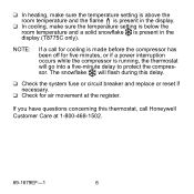
... if a power interruption occurs while the compressor is present in the display (T8775C only). NOTE: If a call Honeywell Customer Care at the register. ❑ In heating, make sure the temperature setting is above the room temperature and the flame is present in the display. ❑ In cooling, make sure the temperature setting is below the room temperature and a solid snowflake is running, the thermostat will go...
... if a power interruption occurs while the compressor is present in the display (T8775C only). NOTE: If a call Honeywell Customer Care at the register. ❑ In heating, make sure the temperature setting is above the room temperature and the flame is present in the display. ❑ In cooling, make sure the temperature setting is below the room temperature and a solid snowflake is running, the thermostat will go...
Owner's Manual
Page 8
Honeywell Limited-Honeywell Limitée 1985 Douglas Drive North 35 Dynamic Drive Golden Valley, MN 55422 Scarborough, Ontario M1V 4Z9 69-1679EF-1 J.S. Rev. 6-04 Printed in Mexico www.honeywell.com/yourhome Automation and Control Solutions Honeywell International Inc.
Honeywell Limited-Honeywell Limitée 1985 Douglas Drive North 35 Dynamic Drive Golden Valley, MN 55422 Scarborough, Ontario M1V 4Z9 69-1679EF-1 J.S. Rev. 6-04 Printed in Mexico www.honeywell.com/yourhome Automation and Control Solutions Honeywell International Inc.
Installation Instructions
Page 1
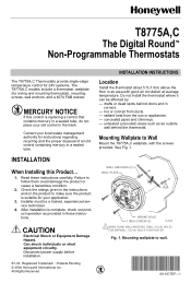
...,C The Digital Round™ Non-Programmable Thermostats The T8775A,C Thermostats provide single-stage temperature control for 24V systems. The T8775A,C models include a thermostat, wallplate (for instructions regarding recycling and the proper disposal of an old control containing mercury in a sealed tube. INSTALLATION When Installing this control is replacing a control that contains mercury in an area with the screws provided. Disconnect power supply before installation. ® U.S. All Rights Reserved WALL ANCHORS (2) WALL PLATE 1 WIRING HOLE 1 INCH...
...,C The Digital Round™ Non-Programmable Thermostats The T8775A,C Thermostats provide single-stage temperature control for 24V systems. The T8775A,C models include a thermostat, wallplate (for instructions regarding recycling and the proper disposal of an old control containing mercury in a sealed tube. INSTALLATION When Installing this control is replacing a control that contains mercury in an area with the screws provided. Disconnect power supply before installation. ® U.S. All Rights Reserved WALL ANCHORS (2) WALL PLATE 1 WIRING HOLE 1 INCH...
Installation Instructions
Page 2
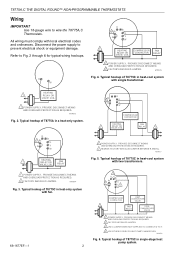
... G R Y W 1 HEATING COMPRESSOR FAN RELAY OR CONTACTOR RELAY VALVE COIL R W 1 POWER SUPPLY. M19513 Fig. 2. Typical hookup of T8775C in a heat-only system. M19516 Fig. 6. Refer to wire the T8775A,C Thermostats. Typical hookup of T8775A in heat-cool system with local electrical codes and ordinances. Typical hookup of T8775C in single-stage heat pump system. PROVIDE DISCONNECT MEANS AND OVERLOAD PROTECTION AS REQUIRED. 2 FACTORY INSTALLED JUMPER. 3 USE A JUMPER WIRE (NOT SUPPLIED) TO CONNECT W TO Y. 4 USE...
... G R Y W 1 HEATING COMPRESSOR FAN RELAY OR CONTACTOR RELAY VALVE COIL R W 1 POWER SUPPLY. M19513 Fig. 2. Typical hookup of T8775C in a heat-only system. M19516 Fig. 6. Refer to wire the T8775A,C Thermostats. Typical hookup of T8775A in heat-cool system with local electrical codes and ordinances. Typical hookup of T8775C in single-stage heat pump system. PROVIDE DISCONNECT MEANS AND OVERLOAD PROTECTION AS REQUIRED. 2 FACTORY INSTALLED JUMPER. 3 USE A JUMPER WIRE (NOT SUPPLIED) TO CONNECT W TO Y. 4 USE...
Installation Instructions
Page 3
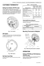
.... 8. Set Heat Cycle Rate Use DIP switches 1 and 2 to set the heat cycle rate. Mounting thermostat to Wallplate ENGAGE TABS AT BOTTOM OF THERMOSTAT AND WALL PLATE. OPERATION Setting SYSTEM and FAN Switches (T8775C only) System and fan settings are controlled manually by using the switches located at the factory in a system where the G terminal is connected. FUEL SWITCH Fig. 7. See Table 2. BACK OF THERMOSTAT Fahrenheit/Celsius Indication Use DIP switch 3 to set the desired temperature indication. Table 1. T8775A,C THE DIGITAL ROUND™ NON-PROGRAMMABLE THERMOSTATS...
.... 8. Set Heat Cycle Rate Use DIP switches 1 and 2 to set the heat cycle rate. Mounting thermostat to Wallplate ENGAGE TABS AT BOTTOM OF THERMOSTAT AND WALL PLATE. OPERATION Setting SYSTEM and FAN Switches (T8775C only) System and fan settings are controlled manually by using the switches located at the factory in a system where the G terminal is connected. FUEL SWITCH Fig. 7. See Table 2. BACK OF THERMOSTAT Fahrenheit/Celsius Indication Use DIP switch 3 to set the desired temperature indication. Table 1. T8775A,C THE DIGITAL ROUND™ NON-PROGRAMMABLE THERMOSTATS...
Installation Instructions
Page 4
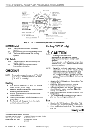
... DIGITAL ROUND™ NON-PROGRAMMABLE THERMOSTATS (T8775C ONLY) SELECTS COOL/OFF/HEAT (T8775C ONLY) SELECTS ON/AUTO ROOM SHOWS THAT THE SET CURRENT ROOM TEMPERATURE IS DISPLAYED. FAN Switch Auto: On: The fan only runs with the heating and cooling system. Cooling (T8775C only) CAUTION Low Temperature Hazard. Refer to Auto. 2. Slide the SYSTEM switch to Cool and the FAN switch to manufacturer's recommendations. Rev. 6-04 Printed in cooling. T8775 Thermostat (features and operation). CHECKOUT NOTE: Temperature setpoint range is...
... DIGITAL ROUND™ NON-PROGRAMMABLE THERMOSTATS (T8775C ONLY) SELECTS COOL/OFF/HEAT (T8775C ONLY) SELECTS ON/AUTO ROOM SHOWS THAT THE SET CURRENT ROOM TEMPERATURE IS DISPLAYED. FAN Switch Auto: On: The fan only runs with the heating and cooling system. Cooling (T8775C only) CAUTION Low Temperature Hazard. Refer to Auto. 2. Slide the SYSTEM switch to Cool and the FAN switch to manufacturer's recommendations. Rev. 6-04 Printed in cooling. T8775 Thermostat (features and operation). CHECKOUT NOTE: Temperature setpoint range is...


