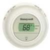
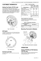
T8775C1005 Manual - Honeywell Digital Round 24V
T8775C1005 Manual
View Results Below
Free Honeywell T8775C1005 manuals!
Problems with Honeywell T8775C1005?
Ask a Question
Free Honeywell T8775C1005 manuals!
Problems with Honeywell T8775C1005?
Ask a Question
Related Manual Pages
Similar Questions

I Downloaded The Softwar To Access The Manual For A Honeywlll Rth230b Thermosta
and now I need the actual manual for this item
and now I need the actual manual for this item
(Posted by drmramor 9 years ago)

Need A Manual For T8112 Thermostat
Need a manual for T8112 Thermostat
Need a manual for T8112 Thermostat
(Posted by julie31366 11 years ago)

Why Cannt I Just Get Owners Manual Without All The Sales Stuff...still Need Manu
JUST WANT MANUAL BUT YOUR SIGHT NEVER GETS ME TO RIGHT SPOT. JUST MORE SALES!!!
JUST WANT MANUAL BUT YOUR SIGHT NEVER GETS ME TO RIGHT SPOT. JUST MORE SALES!!!
(Posted by Applianceliquidators 12 years ago)