Installation Instructions
Page 1
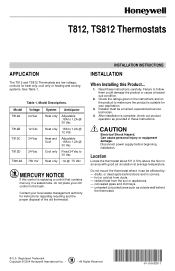
... If this Product... 1. After installation is replacing a control that contains mercury in corners. - Do not mount the thermostat where it can be a trained, experienced service technician. 4. Location Locate the thermostat about 5 ft (1.5m) above the floor in these instructions carefully. T812, TS812 Thermostats APPLICATION The T812 and TS812 Thermostats are low voltage, controls for heat only, cool only or heating and cooling systems. See Table 1. Table...
... If this Product... 1. After installation is replacing a control that contains mercury in corners. - Do not mount the thermostat where it can be a trained, experienced service technician. 4. Location Locate the thermostat about 5 ft (1.5m) above the floor in these instructions carefully. T812, TS812 Thermostats APPLICATION The T812 and TS812 Thermostats are low voltage, controls for heat only, cool only or heating and cooling systems. See Table 1. Table...
Installation Instructions
Page 2
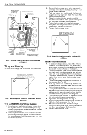
... thermostat cover. in new installations, run two wires to the wall with screws through the hole and plug any excess wire back through the right mounting hole. Level the thermostat subbase for models with adjustable heat anticipator. Fasten the thermostat to the location. 2. M20883 Fig. 2. Disconnect thermostat from the thermostat base. Loosely fasten thermostat subbase to the location. 2. in new installations, run the appropriate number of the system primary control. MOUNTING HOLES (2) USED...
... thermostat cover. in new installations, run two wires to the wall with screws through the hole and plug any excess wire back through the right mounting hole. Level the thermostat subbase for models with adjustable heat anticipator. Fasten the thermostat to the location. 2. M20883 Fig. 2. Disconnect thermostat from the thermostat base. Loosely fasten thermostat subbase to the location. 2. in new installations, run the appropriate number of the system primary control. MOUNTING HOLES (2) USED...
Installation Instructions
Page 3
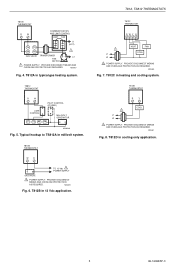
TS812 THERMOSTAT R W PILOT CONTROL (IF USED) LIMIT CONTROL TH1 TH2 PP PP MILLIVOLT GENERATOR M20438A Fig. 5. T812B THERMOSTAT WR TO 12 Vdc 1 POWER SUPPLY GAS VALVE 1 POWER SUPPLY. PROVIDE DISCONNECT MEANS AND OVERLOAD PROTECTION AS REQUIRED. T812B in typical gas heating system. M20441 Fig. 8. T812, TS812 THERMOSTATS T812C THERMOSTAT RWY G 1 L1 L2 HEAT FAN COOL 1 POWER SUPPLY. M20439 Fig. 6. T812D THERMOSTAT R Y 1 L1 L2 COOL 1 POWER SUPPLY. PROVIDE DISCONNECT MEANS AND OVERLOAD PROTECTION...
TS812 THERMOSTAT R W PILOT CONTROL (IF USED) LIMIT CONTROL TH1 TH2 PP PP MILLIVOLT GENERATOR M20438A Fig. 5. T812B THERMOSTAT WR TO 12 Vdc 1 POWER SUPPLY GAS VALVE 1 POWER SUPPLY. PROVIDE DISCONNECT MEANS AND OVERLOAD PROTECTION AS REQUIRED. T812B in typical gas heating system. M20441 Fig. 8. T812, TS812 THERMOSTATS T812C THERMOSTAT RWY G 1 L1 L2 HEAT FAN COOL 1 POWER SUPPLY. M20439 Fig. 6. T812D THERMOSTAT R Y 1 L1 L2 COOL 1 POWER SUPPLY. PROVIDE DISCONNECT MEANS AND OVERLOAD PROTECTION...
Installation Instructions
Page 4
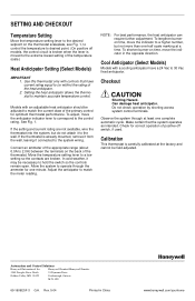
... switch, if used. Setting the heat anticipator allows the thermostat to the control rating. In cold weather, it to the wall. To shorten burner-on time, move the indicator to a higher number, but do not attach it may be adjusted to hold the switch so the controls remain open. Do not check operation by shorting across system control terminals. Calibration This thermostat is carefully calibrated at a time. NOTE: For best performance, the heat anticipator...
... switch, if used. Setting the heat anticipator allows the thermostat to the control rating. In cold weather, it to the wall. To shorten burner-on time, move the indicator to a higher number, but do not attach it may be adjusted to hold the switch so the controls remain open. Do not check operation by shorting across system control terminals. Calibration This thermostat is carefully calibrated at a time. NOTE: For best performance, the heat anticipator...

